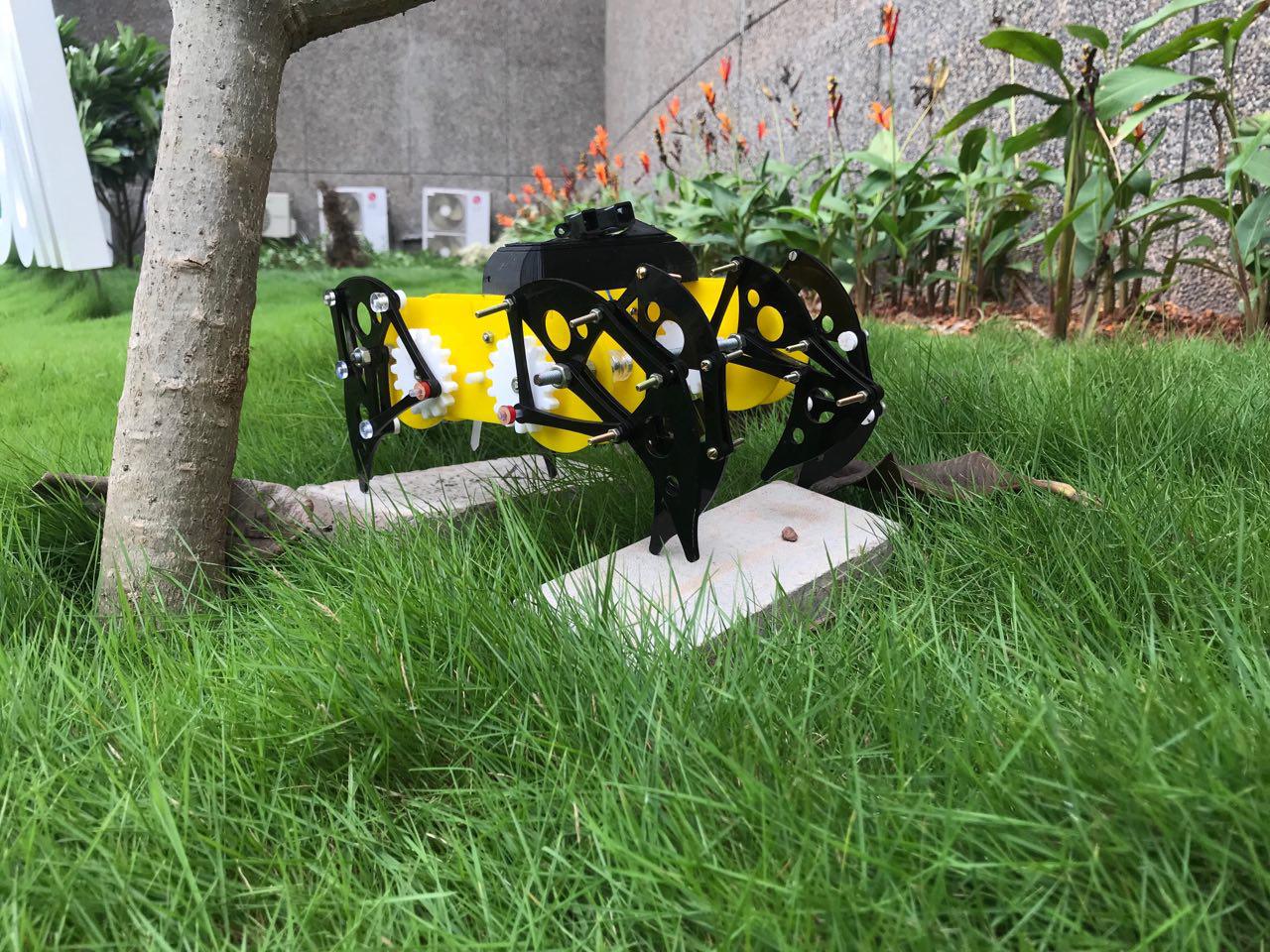
Mechabeest
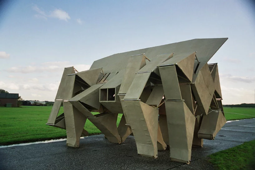
So I choose Mechabeest as my final project. Mechabeest is just a strandbeest. As I described in the first week, the Strandbeest mechanism is a ratio of linkages that creates motion similar to the naturural motion of animals or other beings. Now I have to cordinate all the things I learned from the past weeks to make this strandbeest. So lets get started...
Introduction
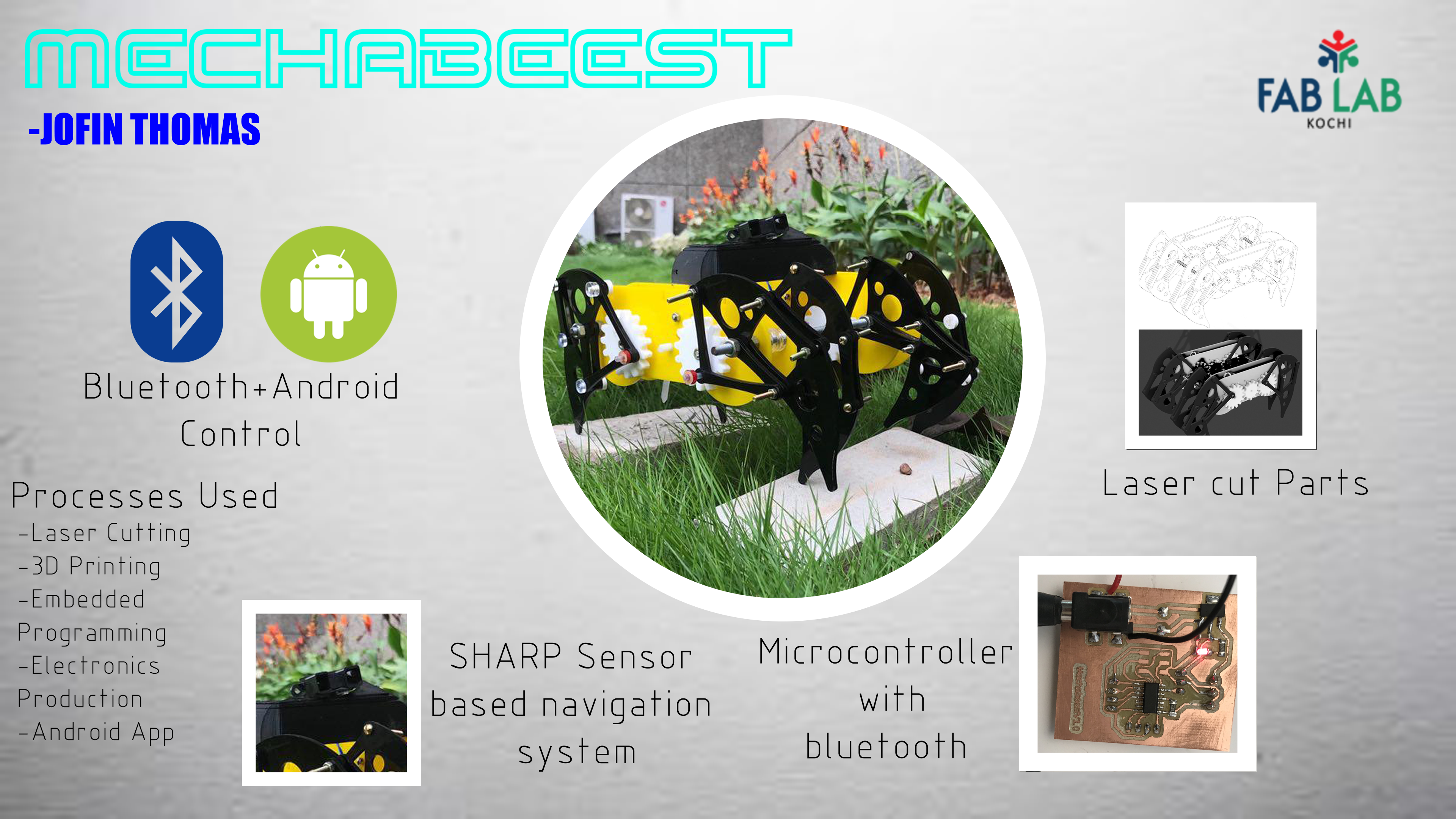
So As I said, strandbeest mechanisn is very simple to understand. But getting it to the right ratio is challenging. The whole mechanism can be failled is a value is out of its original value. Here my chanllenge is to make a strandbeest mechanism that can be controlled using remote control and self navigate without human guidance. I have to design the mechanism, and electronics for project.
The processes that I am going to use for my projects are listed below..
So let's make it....
The Mechanism
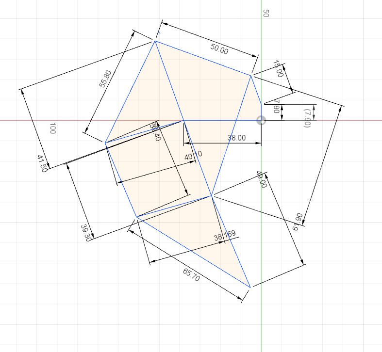
Theo Jenson mechanism is pretty simple to understand and bit difficult get the correct outcome. So the is a perfect ratio for making a strand beest. The n eI used is given below..
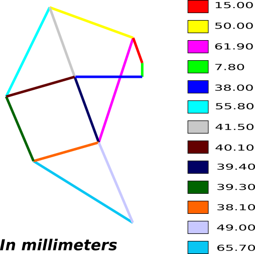
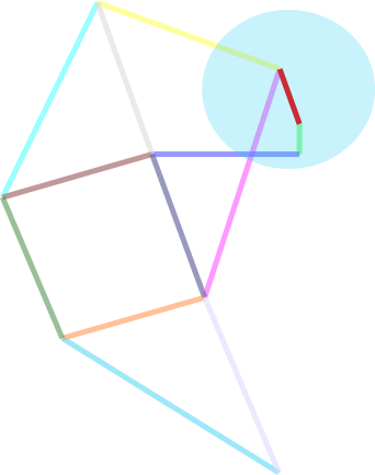
Most of these parts are moving parts except the grounded ones. The grounded parts act as a support frame for the whole mechanism. Here is the the grounded parts.
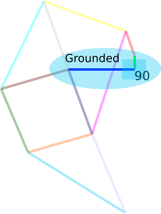
The whole links move using asingle crank that attached to the grounded parts. Below I have highlighed the crank..
Now we have the mechanism's ratio. So let's design the whole Strandbeest.....
Designing
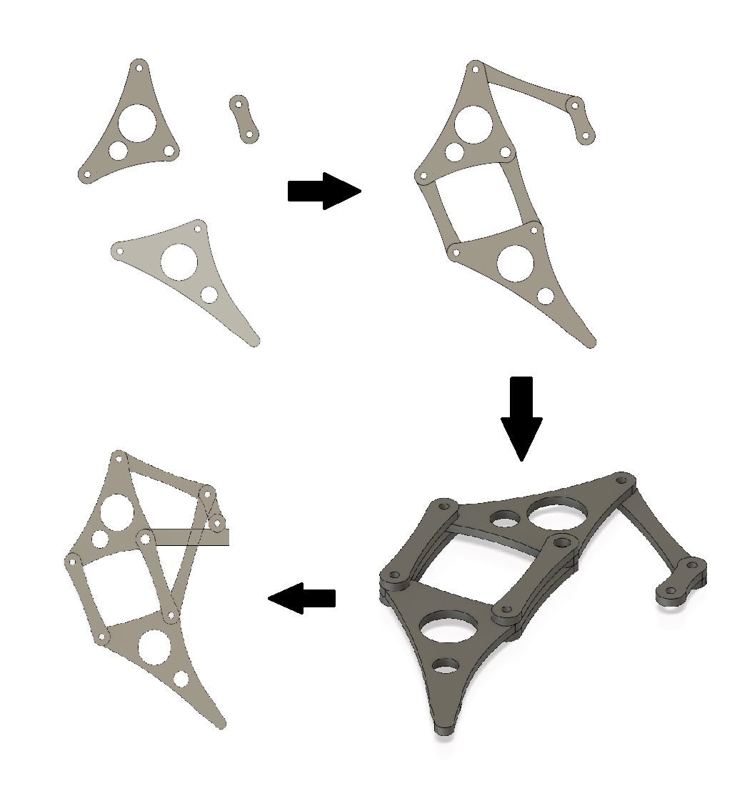
I have been using Fusion 360 from the begining of the academy. So the experience that I gain from the privious experience helped me to complete teh designing in a small amount of time. I started by drawing the basic design from the above design.
The basic design is just a skeleton for the oringinal design. So I have Includes the body and holes for the shafts.
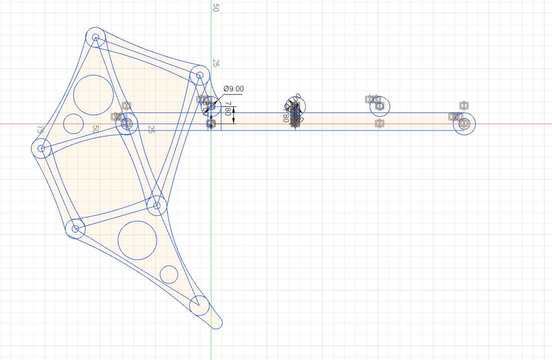
I have included every body in one sketch so I had to extrude them in multiple trys..
Now I have to simulate the motion of the mechanism For that I Joined each componets with Joint option. Before that I grounded the part that need to be grounded.
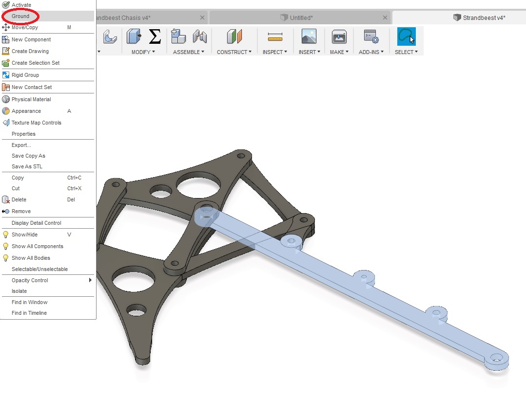
The ground is in place So now I can joint the components to gether...
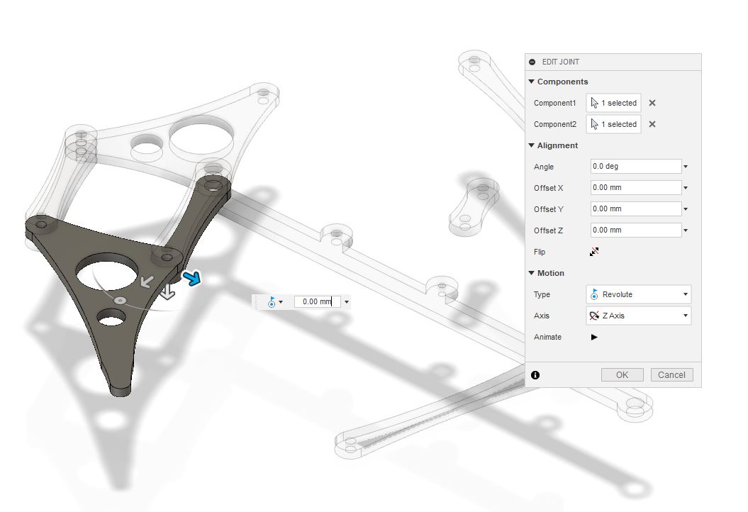
Last joint the crank..
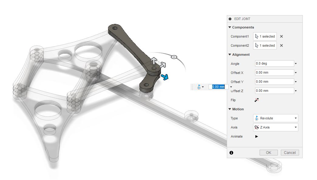
Now I tried to move the mechanism by turning the crank and it worked perfectly.
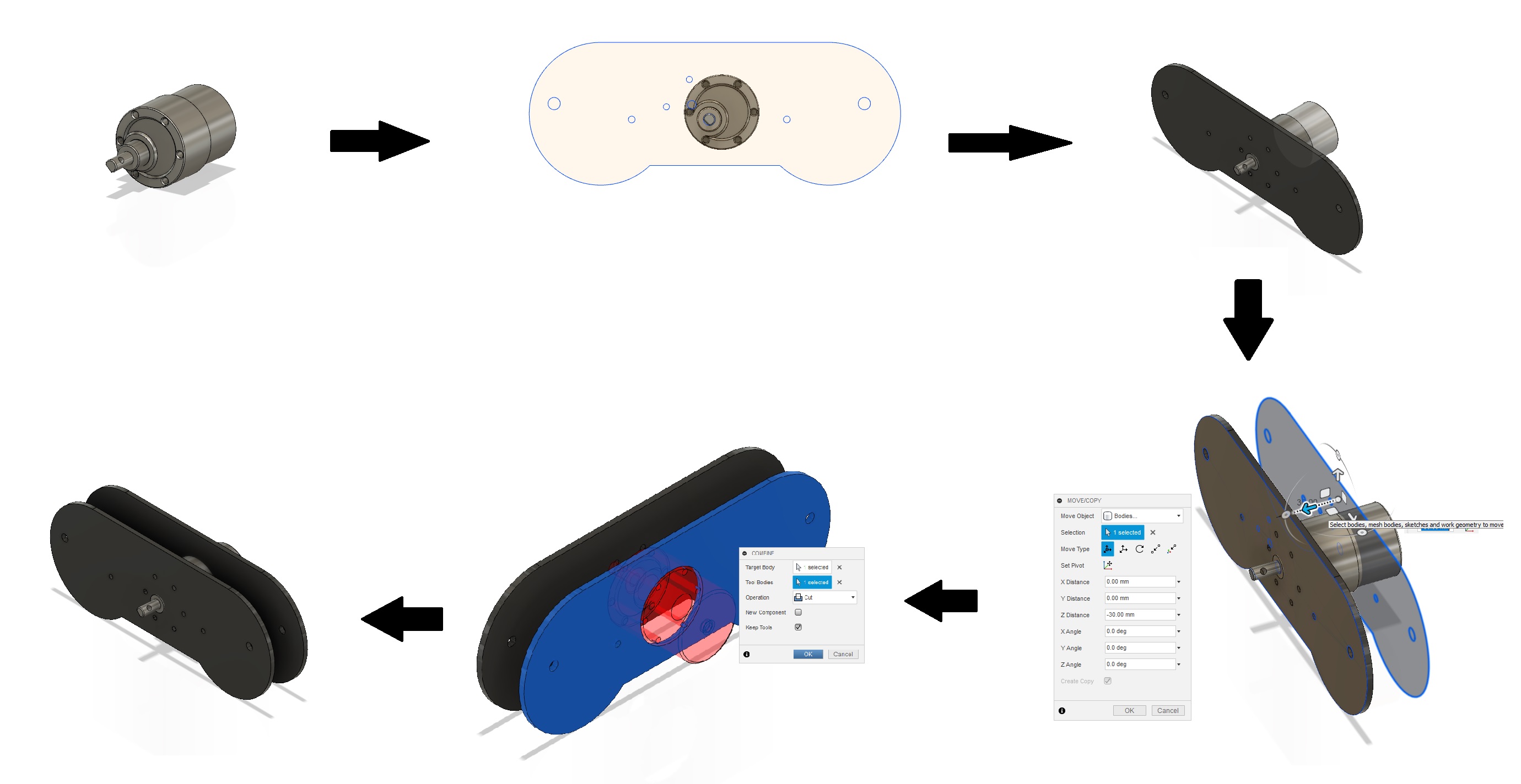
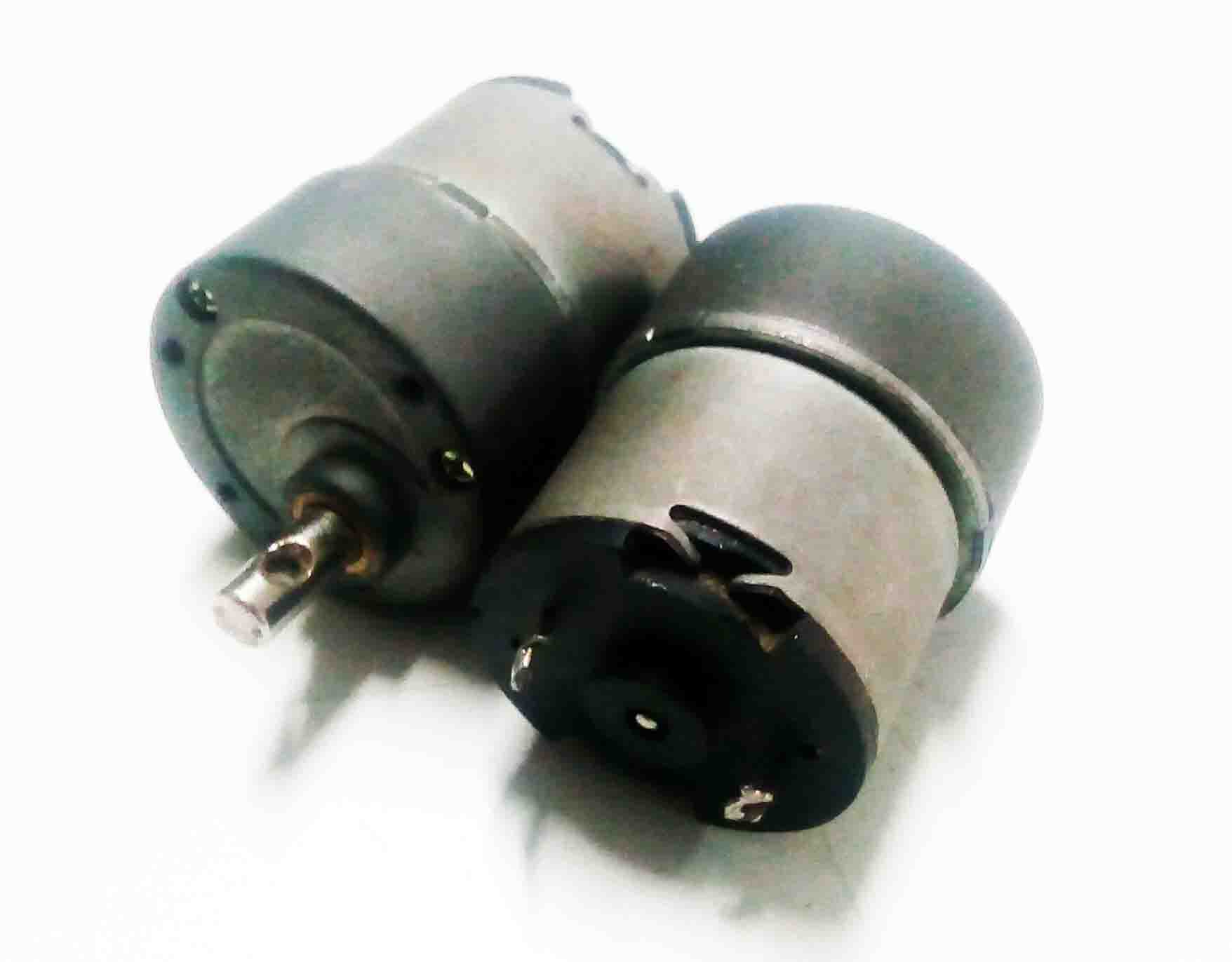
Perfect! Now I can design the chassis + housing unit for motors and electronics parts. For that I first Imported a bo motor file from GrabCAD.
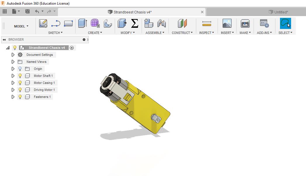
Now start a new sketch with refference to one face of the bo motor. After that extrude to a thickness of 3mm.
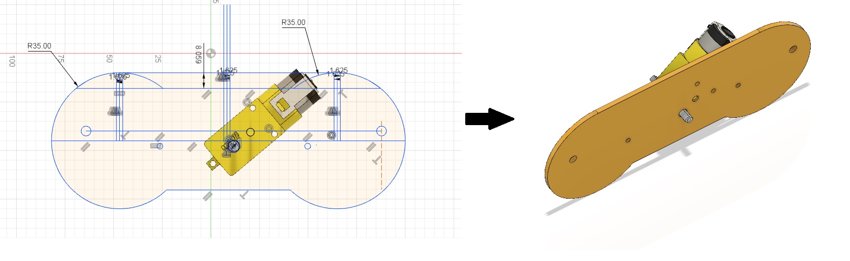
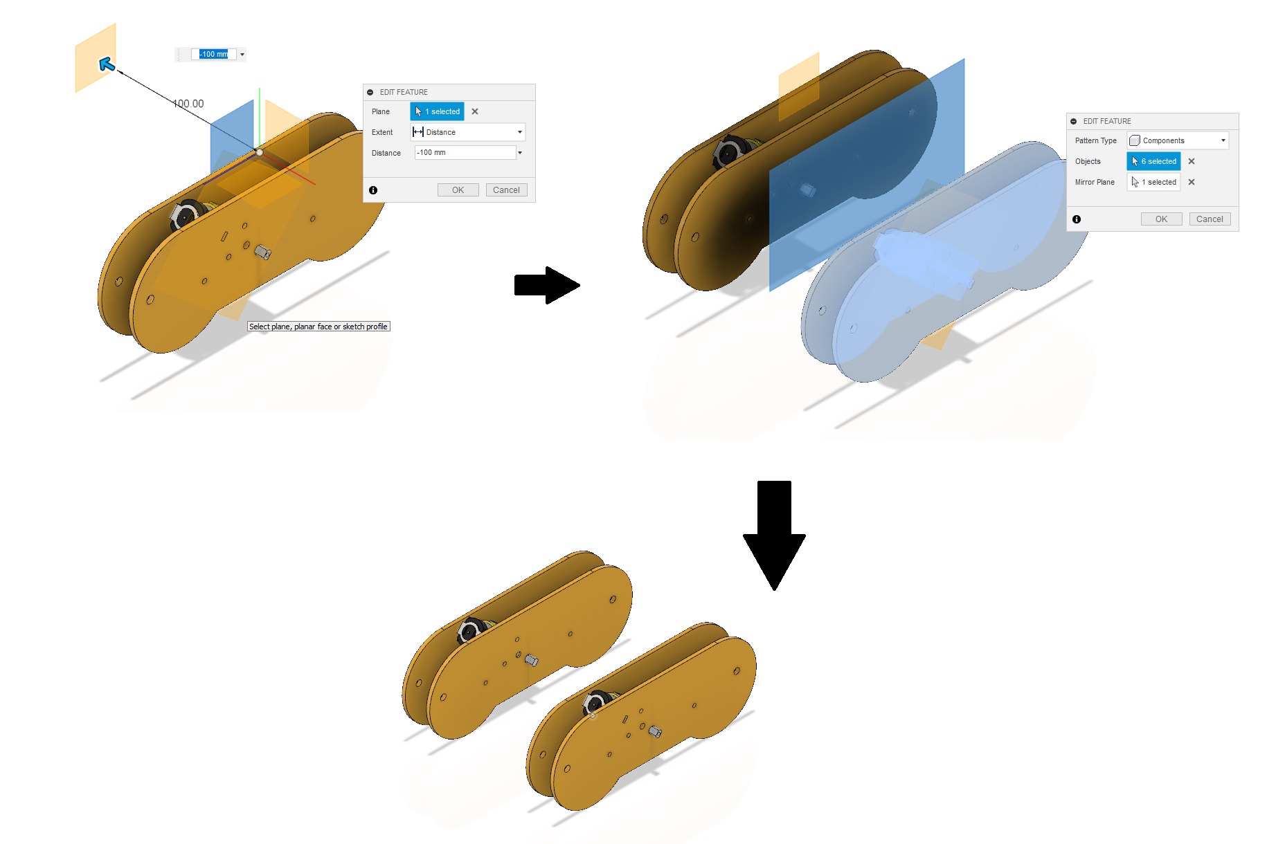
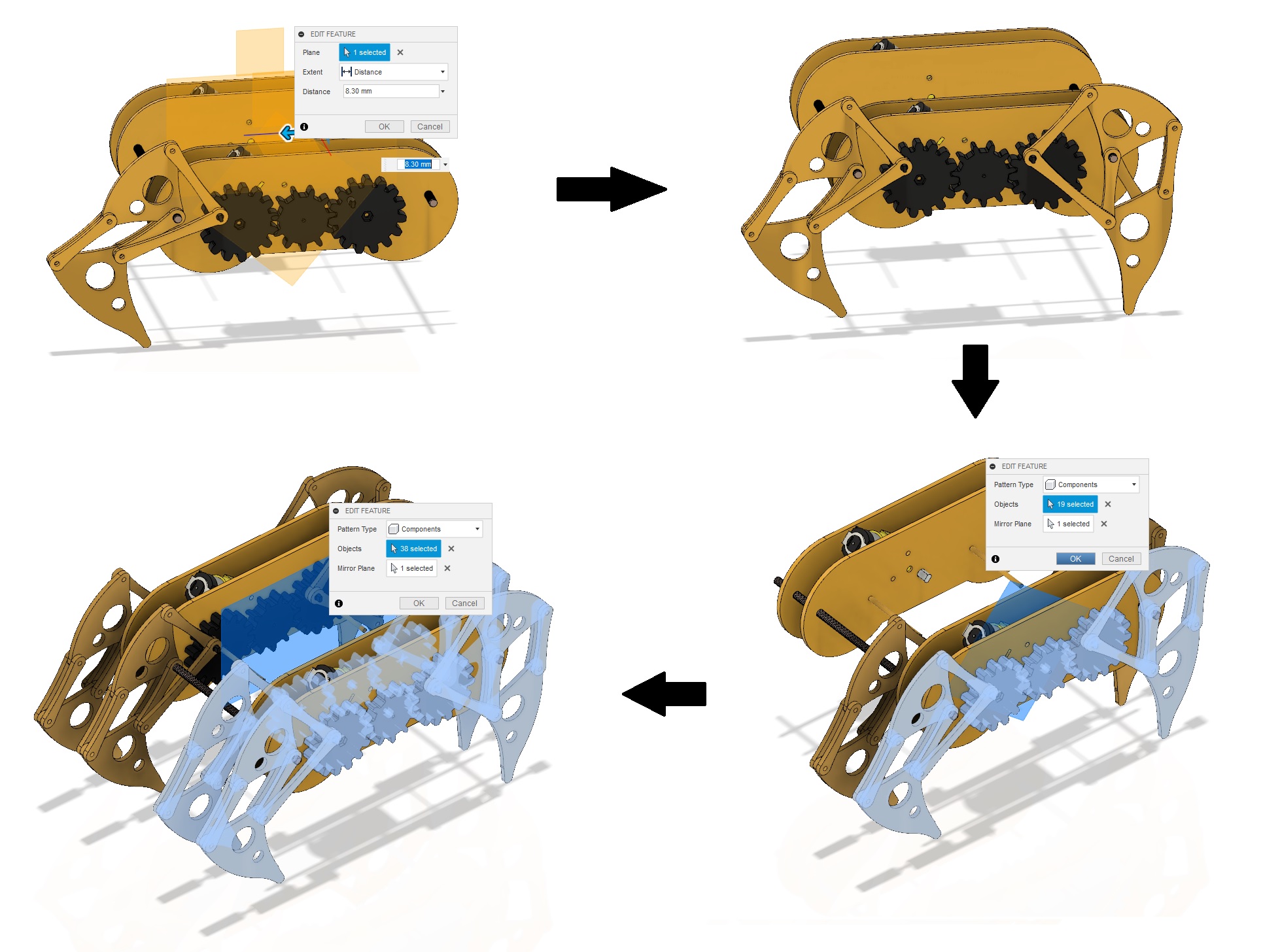
I need a same part on the other side of the motor. For that I created a midplane between the two faces of the bo motor and mirror the part using mirror tool.
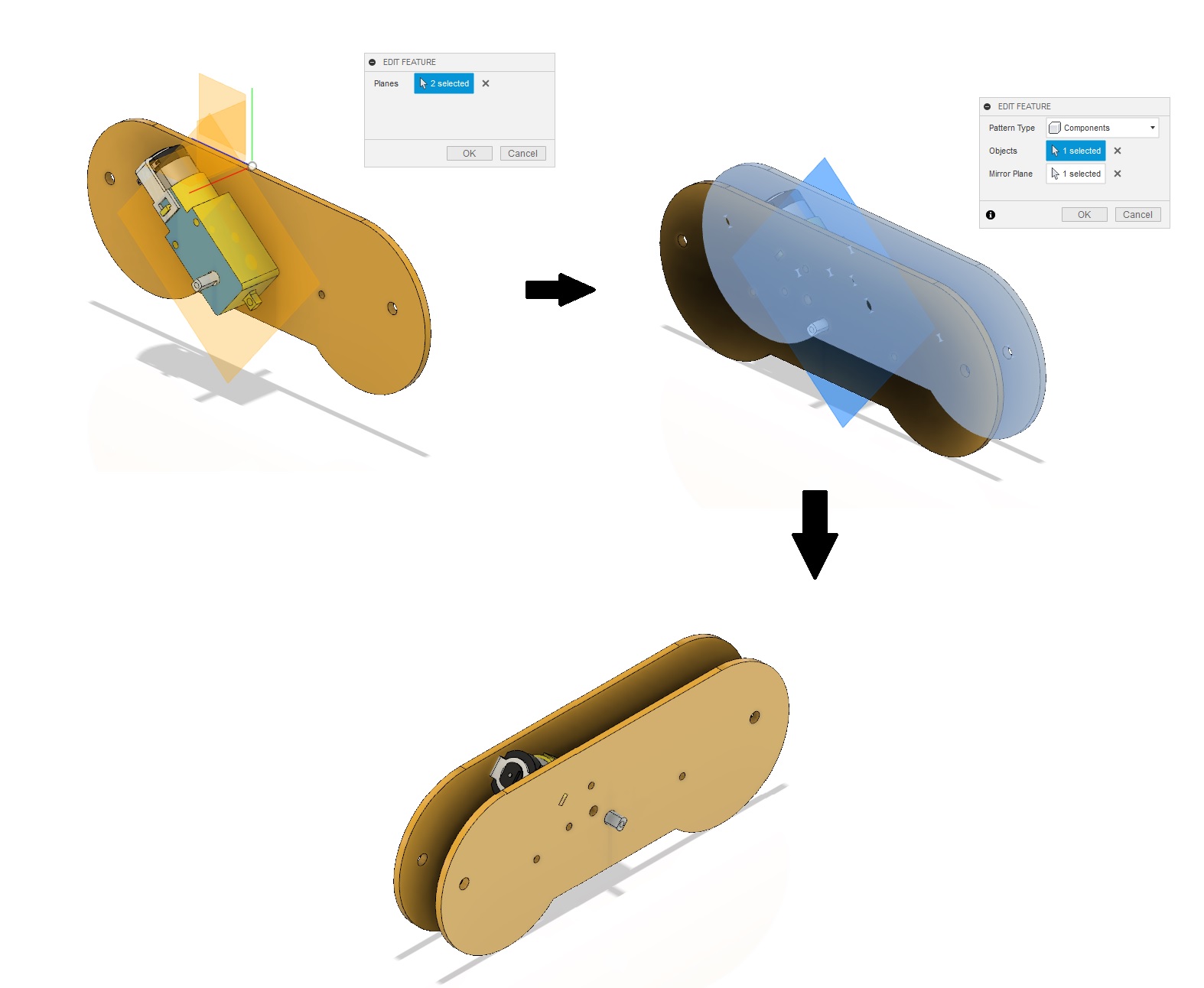
Repeat the same processes to create the same set of bodies to the other side
After that ground the components. Now I have to connect these set of components together. For that I selected one side of the chassis and project the sketch. I extride as a cylindrical rod to the other side of the chassis. Also add tread using Tread Tool.
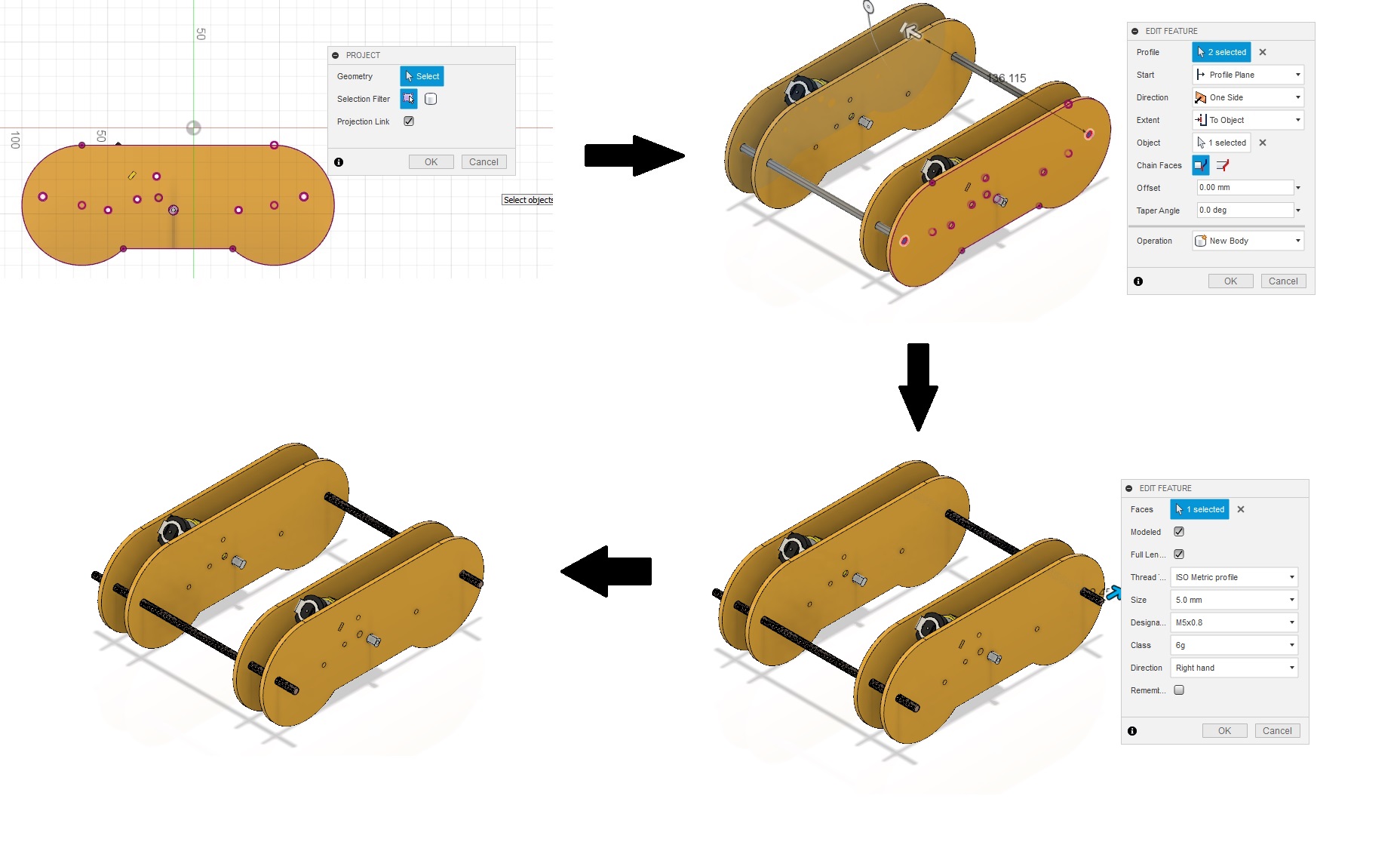
Now I extrude rods for connecting the crank.
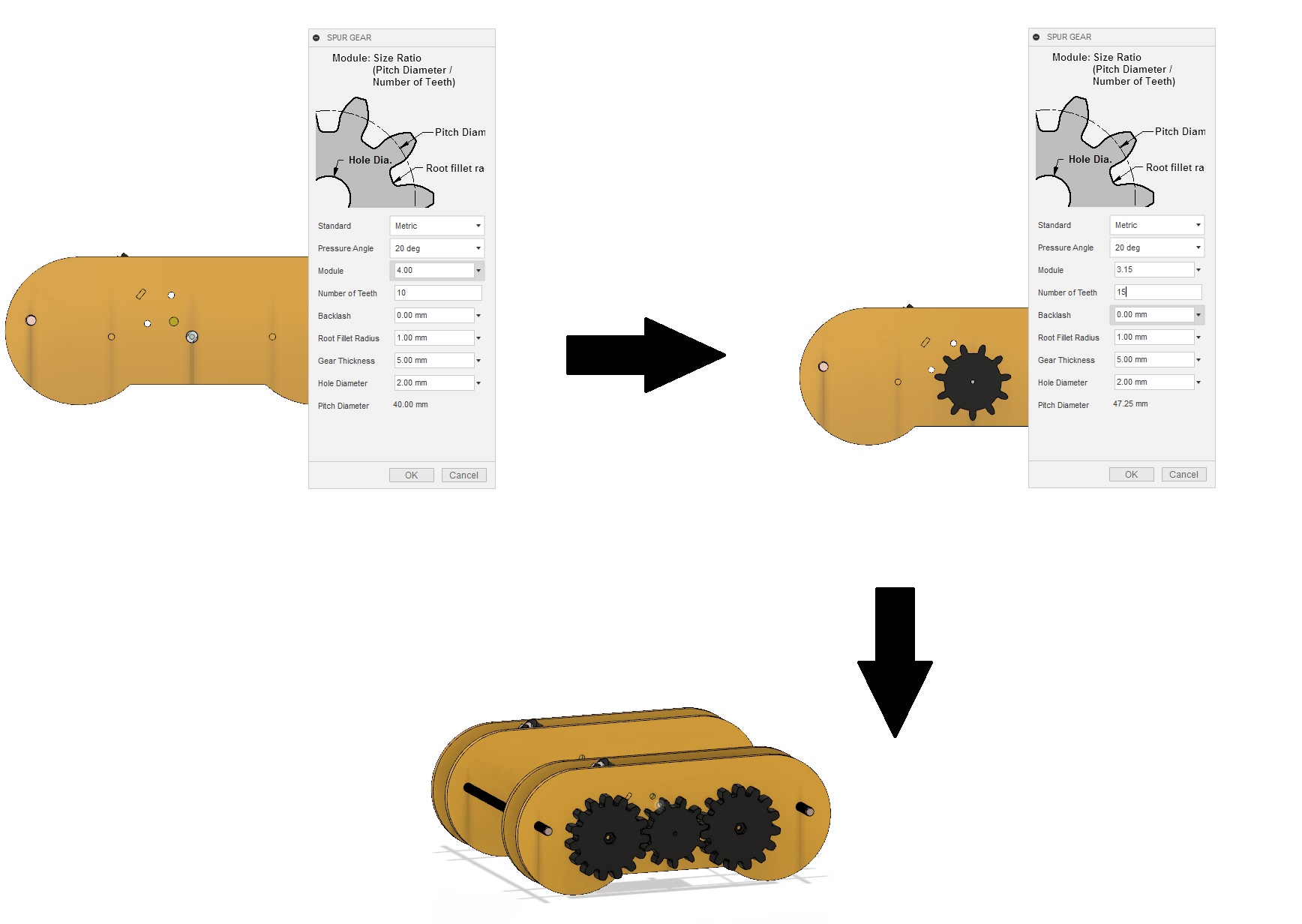
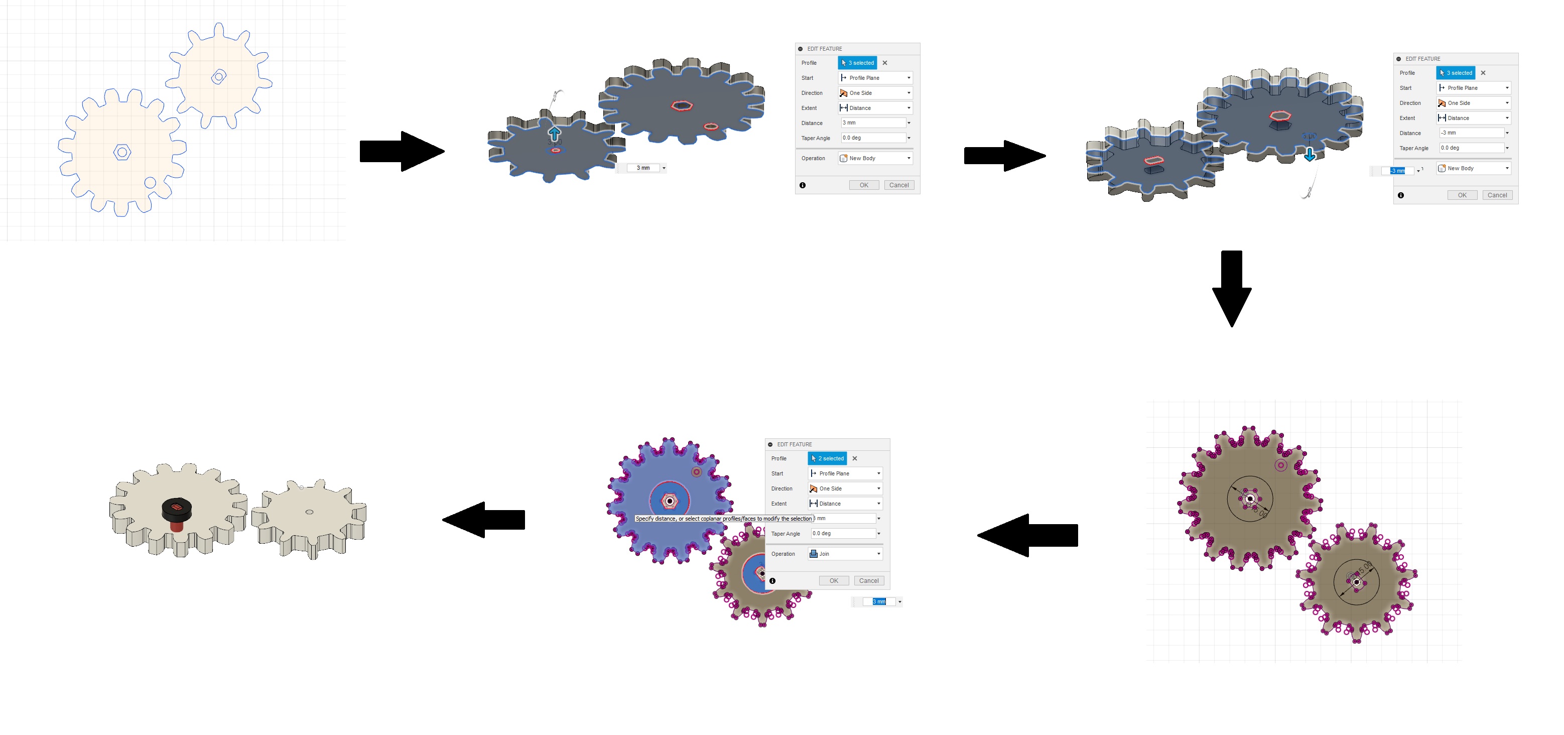
I need to make gears for the drive. For that I use Spure Gear from add Ins. I have created two gears. One with 10 teeth for bo motor and one with 15 teeth for the crank mechanism.
I Imported the strandbeest linkage from the other page to chasis page and assemble it with respect to the chassis

Now I mirror the legs with respect to multiples planes. I mirror the legs to all the faces that a shaft is included.
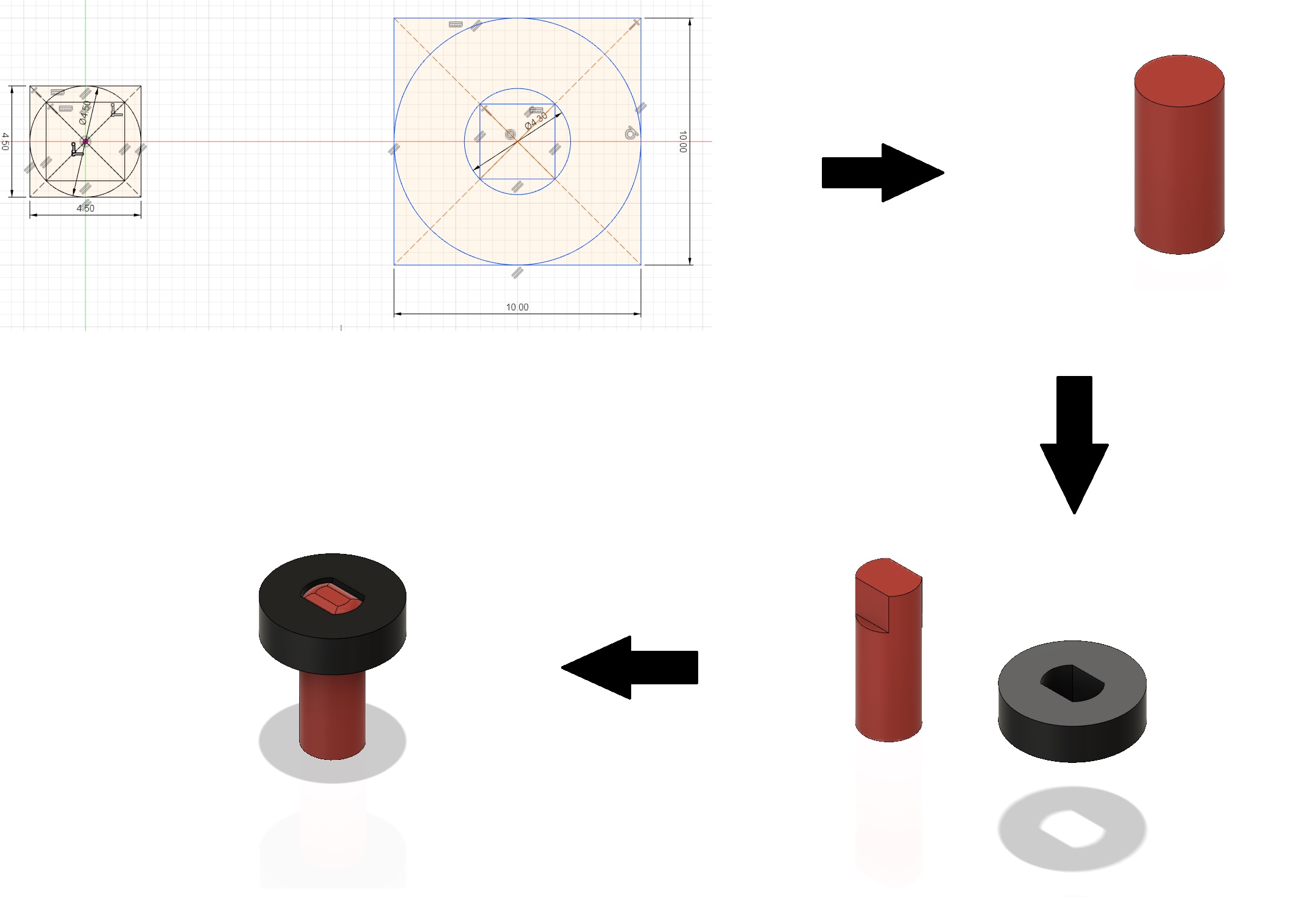
I also need to make gears and crank mechanism. I desided to make them also. For that I first design a lock gear mechanism. I started with a basic sketch that include a shaft and a stopper. I extrude the shaft to 9mm and stopper as 3mm.
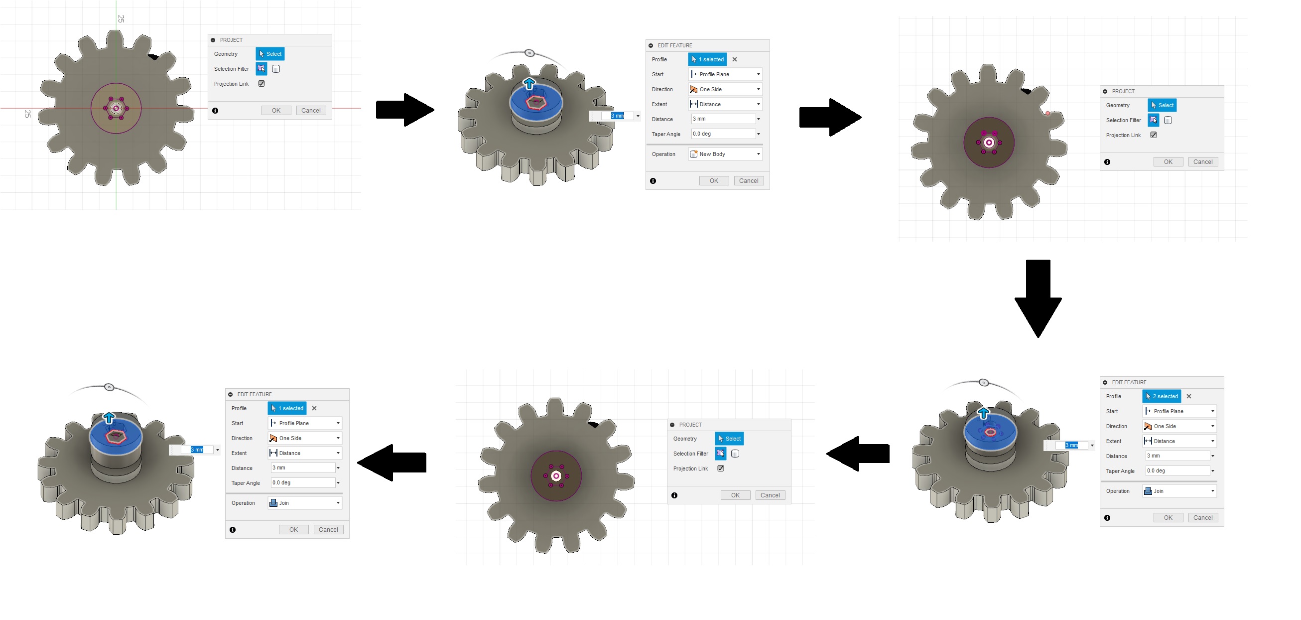
I have already made the gears using spur gear add in. I took its sketch and extrude with multiple inner hole shapes (hexagon for nut and circle for the bolt) between the intervals of 3mm each.
I also need to make gears and crank mechanism. I desided to make them also. For that I first design a lock gear mechanism. I started with a basic sketch that include a shaft and a stopper. I extrude the shaft to 9mm and stopper as 3mm. I also joined the shaft to the gear.
Now All I need is a stopper mechanism to hold the shaft gears on the other side of the chassis. For that I made a 15mm stopper with hexagonal nut holders at both sides with 9mm thickness.
I also need to make gears and crank mechanism. I desided to make them also. For that I first design a lock gear mechanism. I started with a basic sketch that include a shaft and a stopper. I extrude the shaft to 9mm and stopper as 3mm.
You can download the the files from Here...
Now let's move to assembly.....
Mechanical Production and Assembly
I have successfully designed the mechanism. Now I need to make it. Here I am going to make the parts using two machine processes.
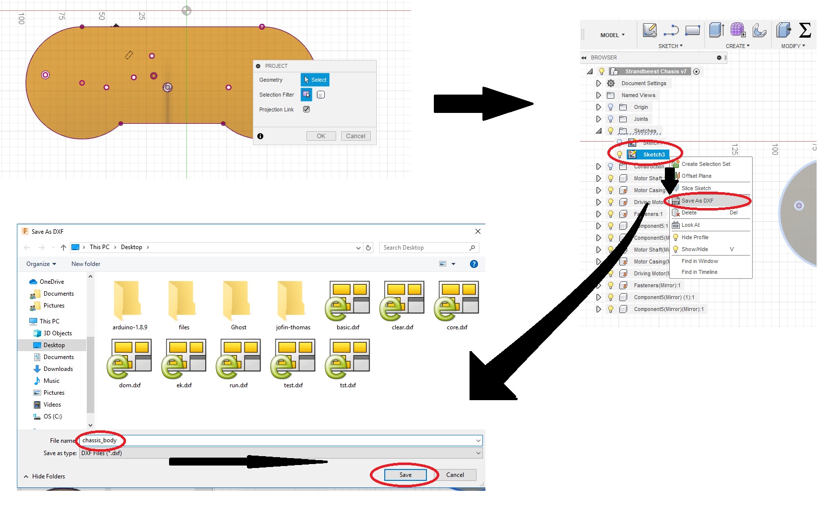
So first I need to convert the design for manufacturing. For laser cutting I have took out .dxf files from fusion 360 and for 3D printing .stl file is exported.
For exporting .dxf file first we have to take the projection sketch of a full body. Then go to sketch and right click for save .dxf file.
For expoting .stl file go to make option and select 3D Print. Save to desire name.
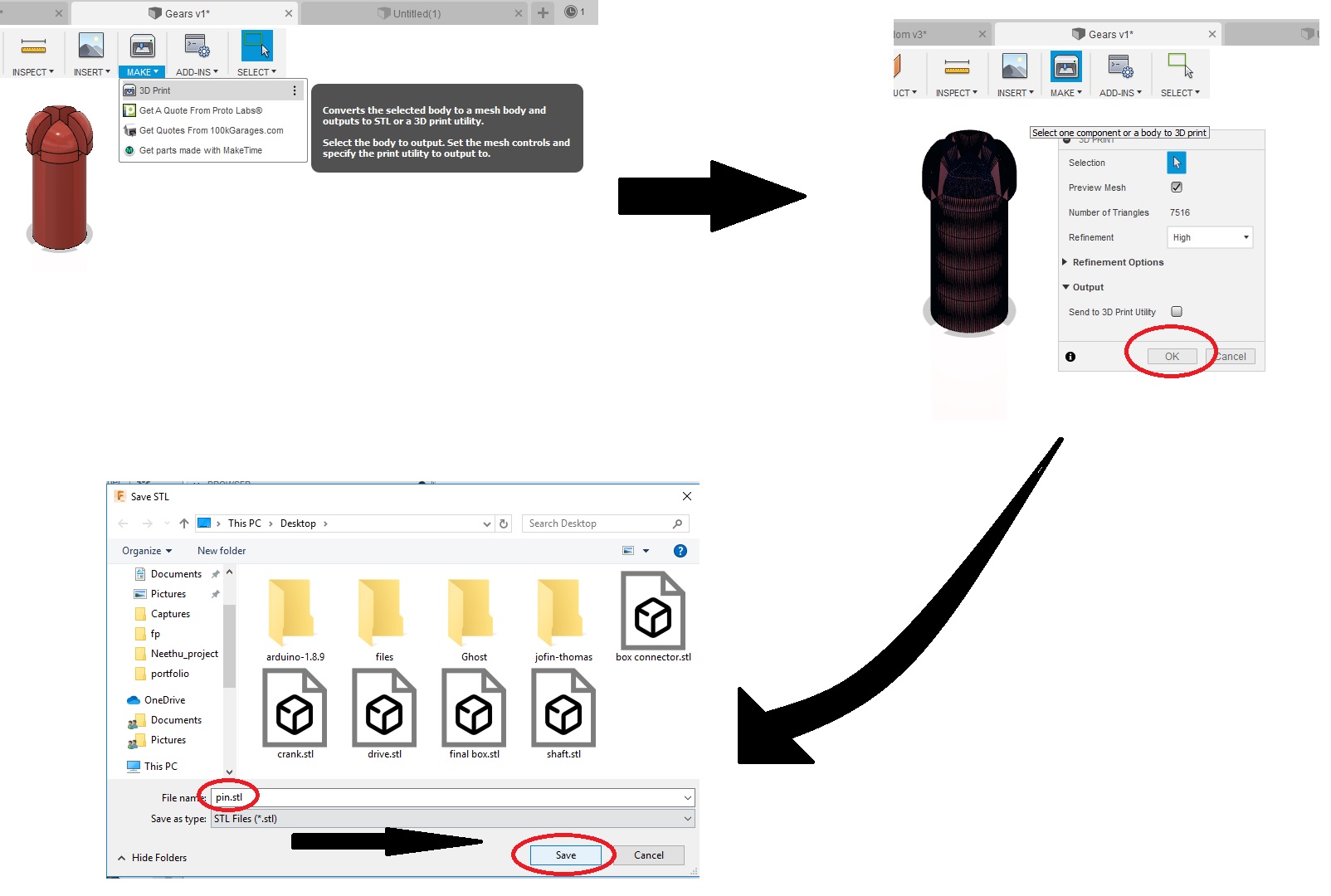
In this way I have export all the files required. You can download the the files from Here
3D Printing
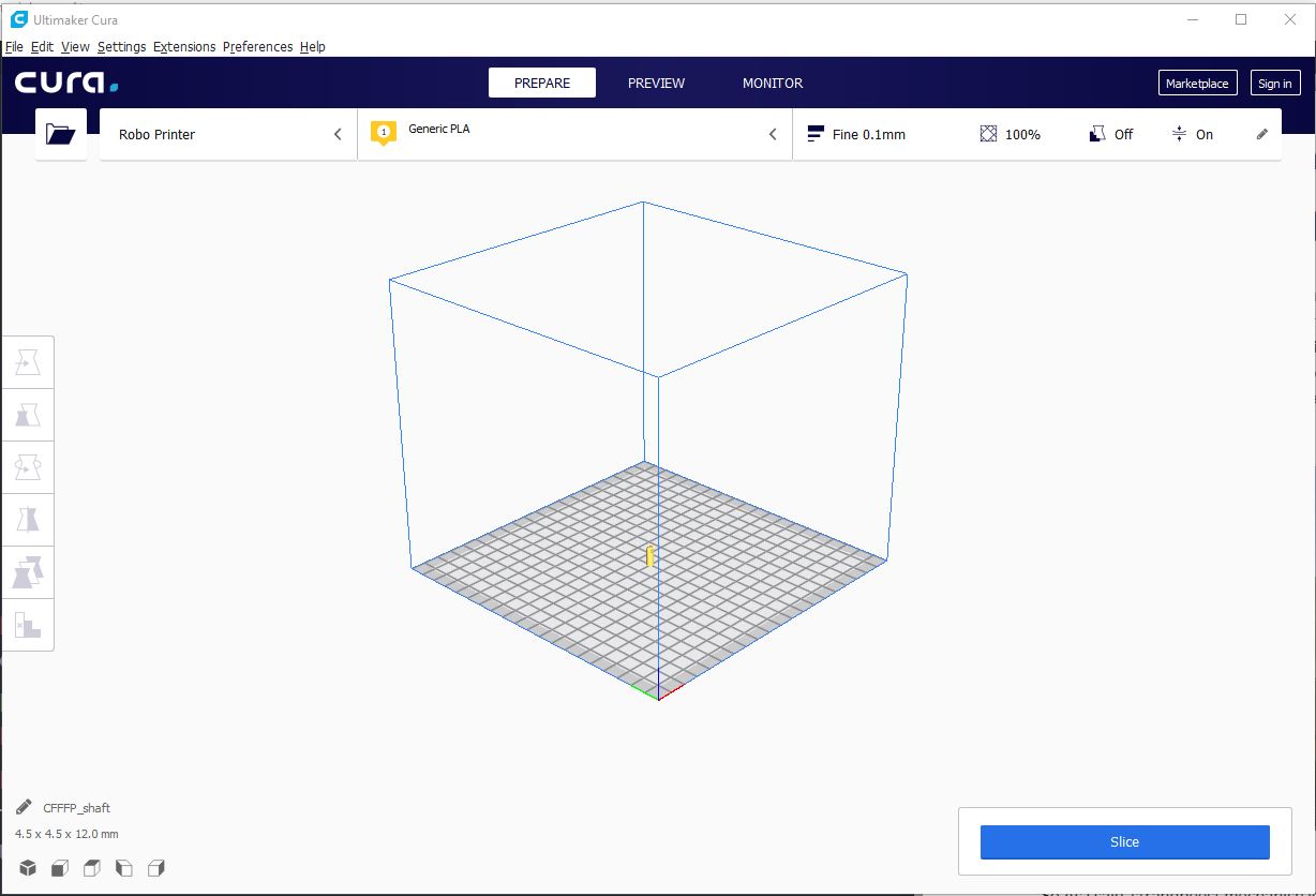
There is just one part that now needed to print. So I started woth that. For slicing ultimaker, I have used "Ulitimaker Cura 4.0". I opened Cura and import pin.stl
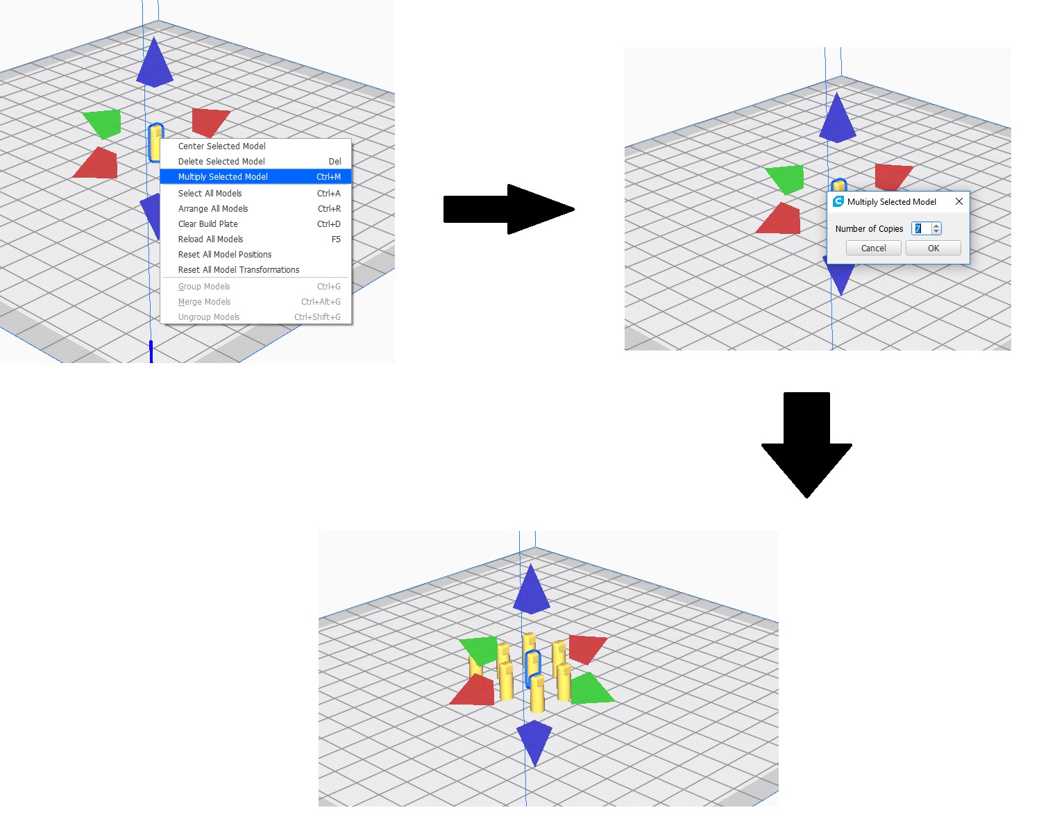
There is only one pin. I needed 8 pins. So I use multiple option to replicate the pin. For that press Ctrl+M or right click.Select the number of copies and click ok.
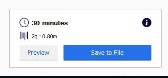
Now go to setting and add as following...
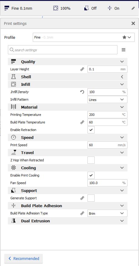
Now click slice and save to SD Card.
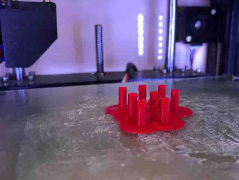
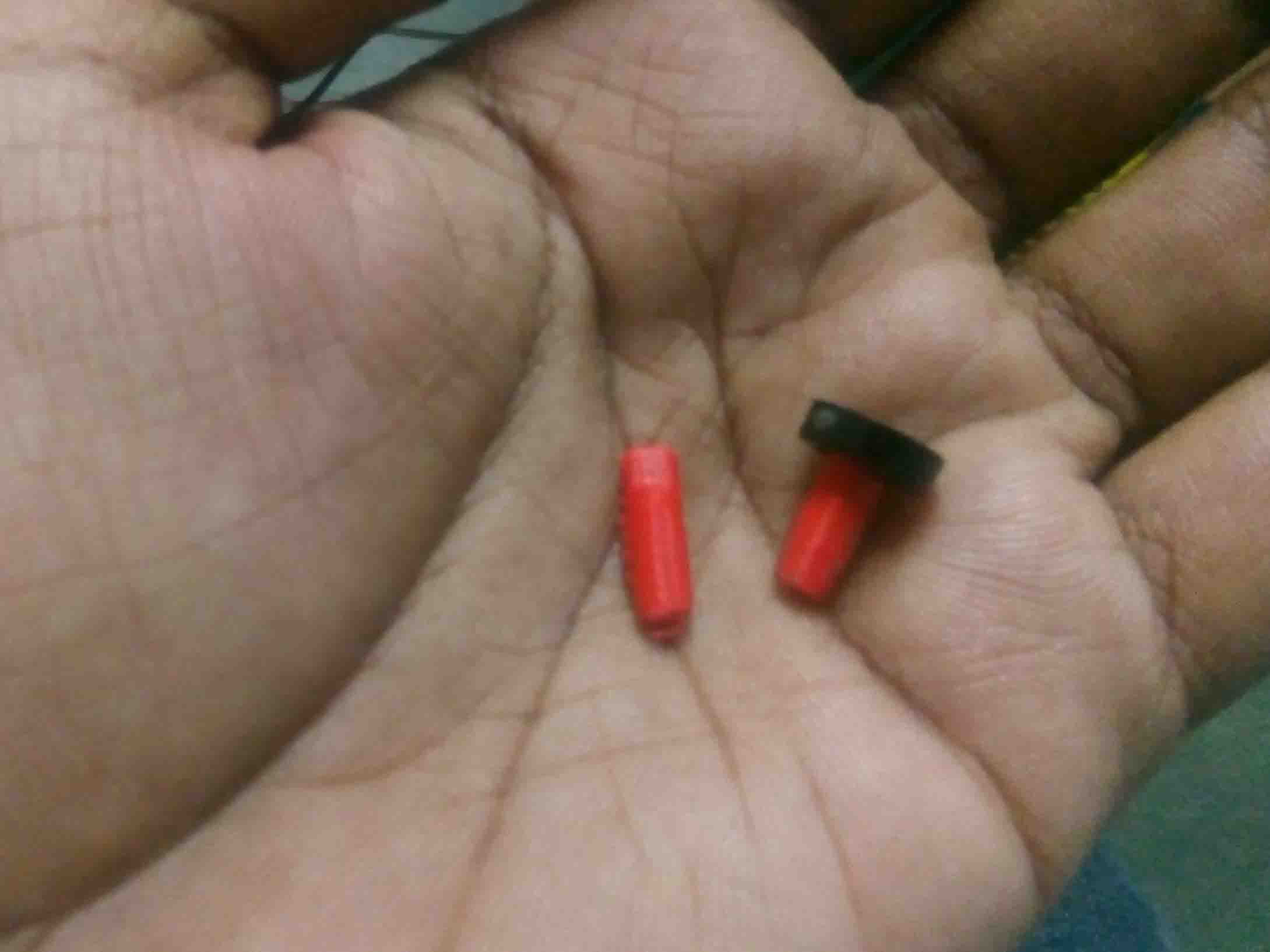
I started printing...
here the stoppers was lasercut
Rest of the parts are needed to be lasercut. So let' get to laser cutting..
Laser Cutting
Most of the parts are made using lasercuting. For laser cutting, I have taken the .dxf files of each components. In our fab lab we are using "Trotec Speedy100". Like a did in Week 4 I had to give different colour to different cuts. So I editted the whole design using Inkscape.
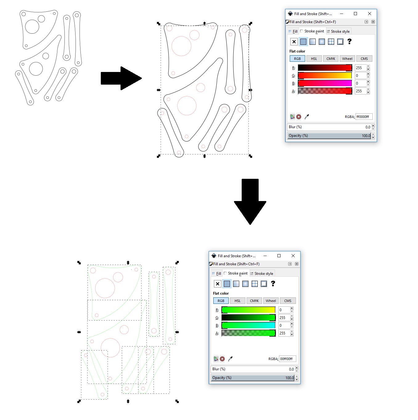
I have given Red for inner circles and holes and Green for outer so that they cut after holes. Then I send to the driver software dfor further editing
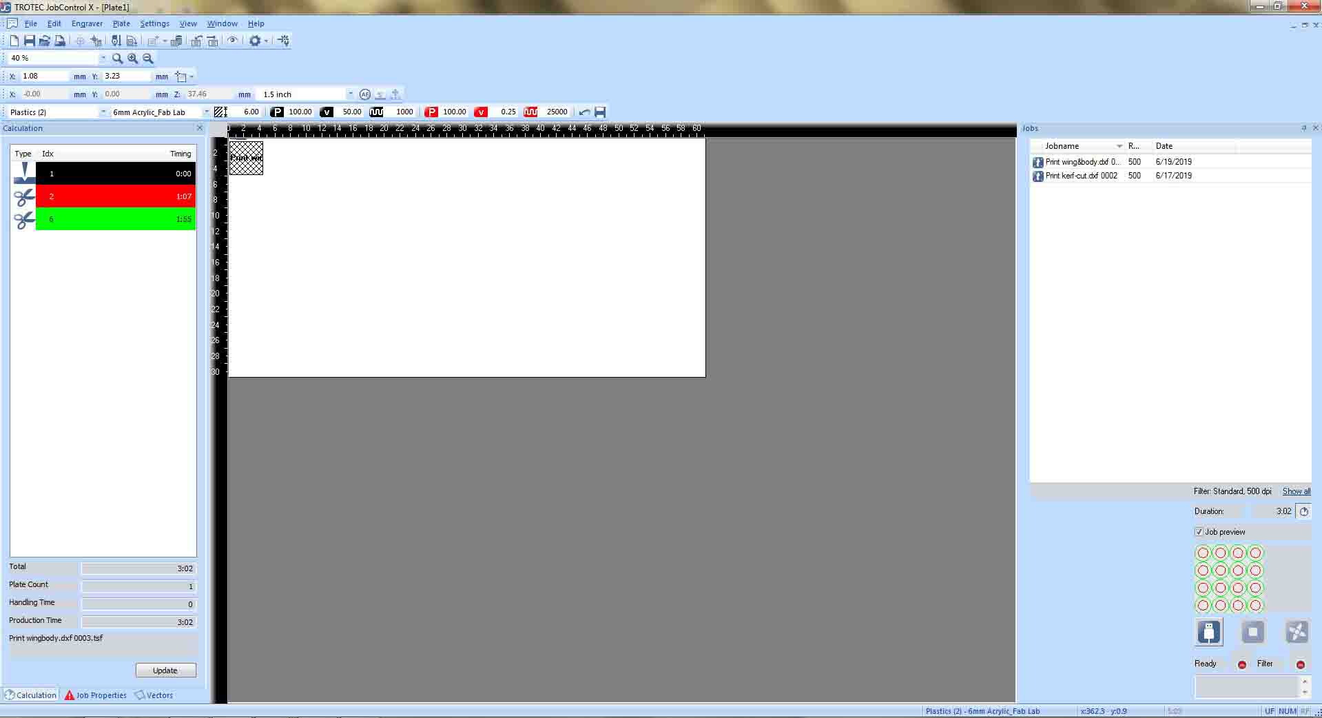
I have selected 3mm acrylic for cutting. Also I set for Red for cut first and Green
at the end.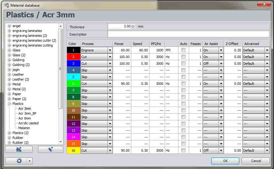
After setting all the axes I started cutting..
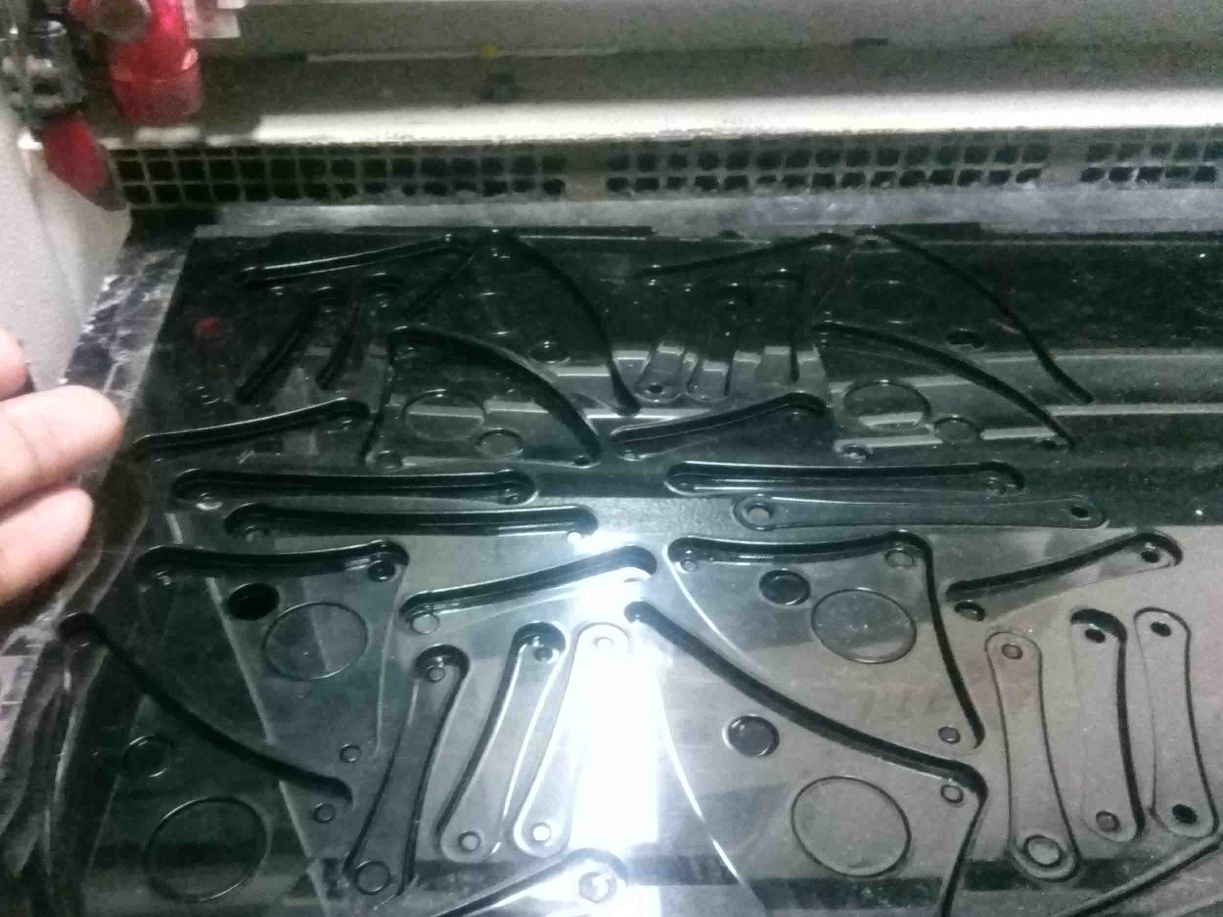
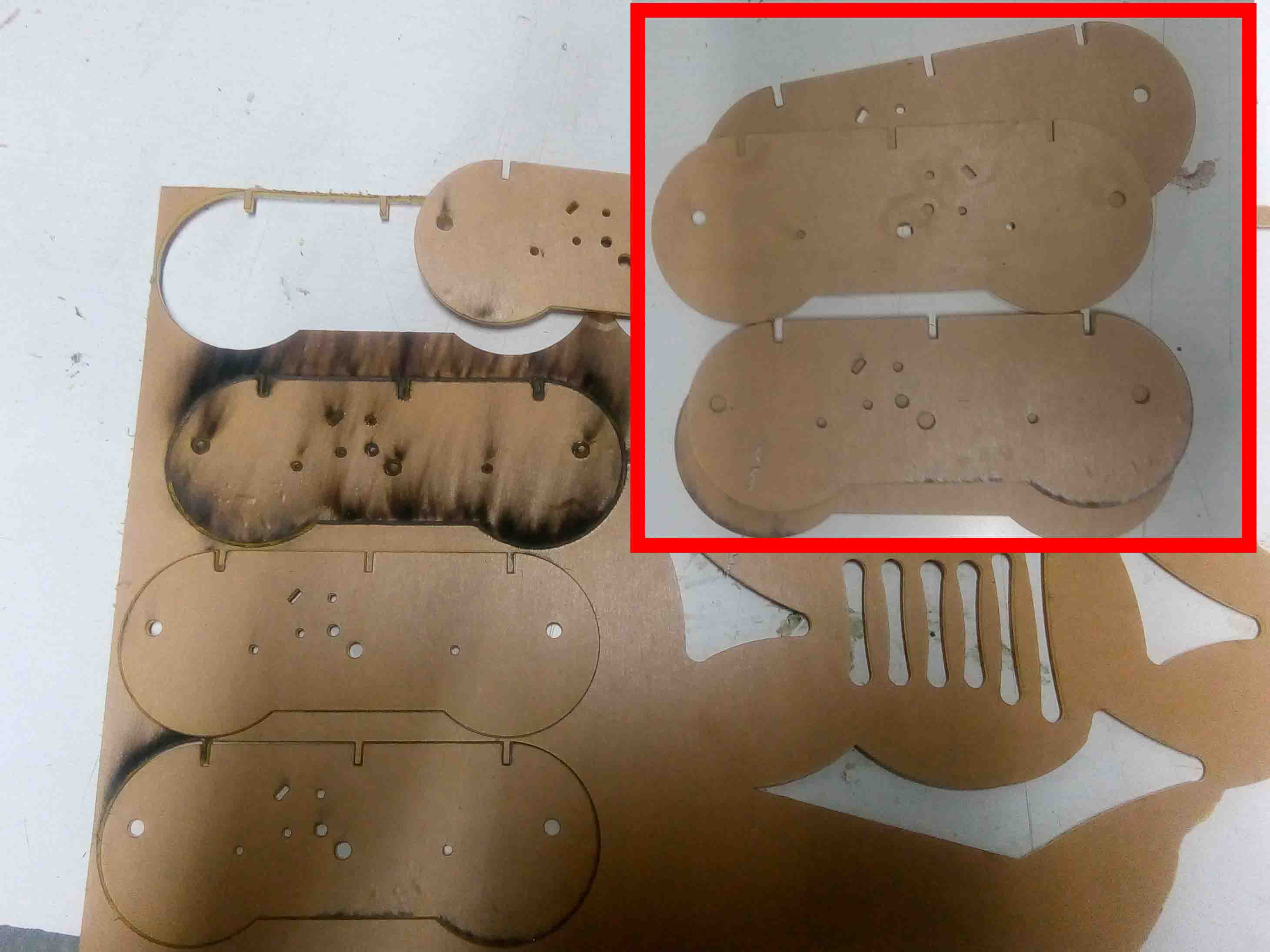
I cut the parts for legs first. I also cut out the chassis body..
Cutting the gears was the best thing..
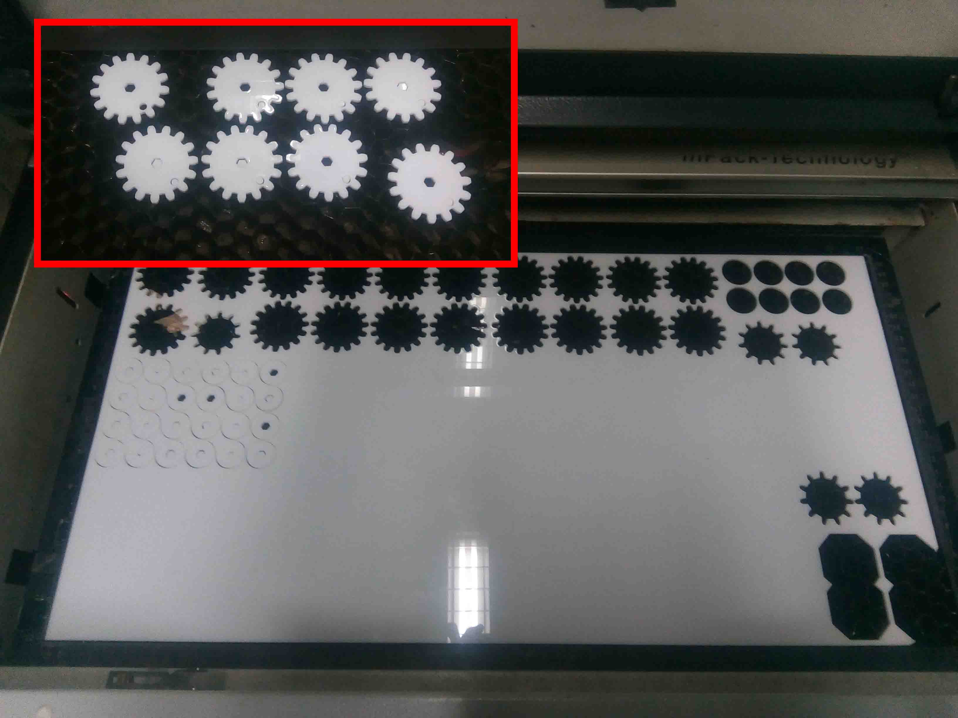
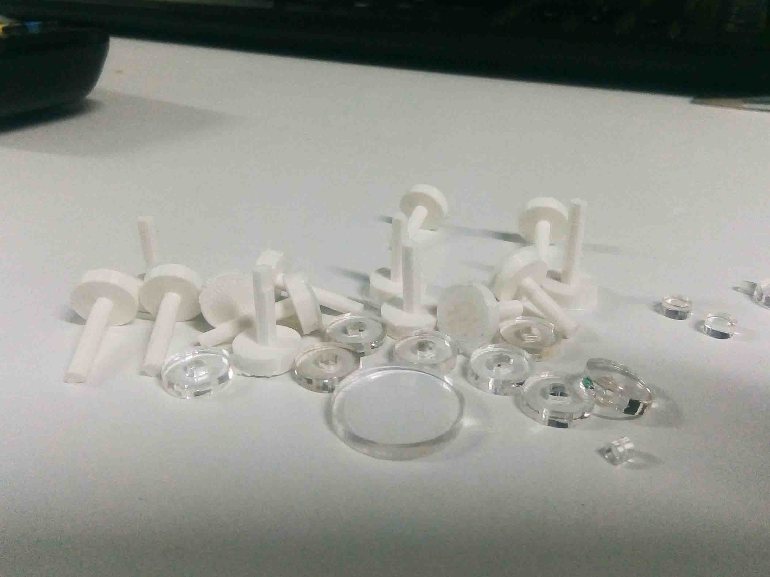
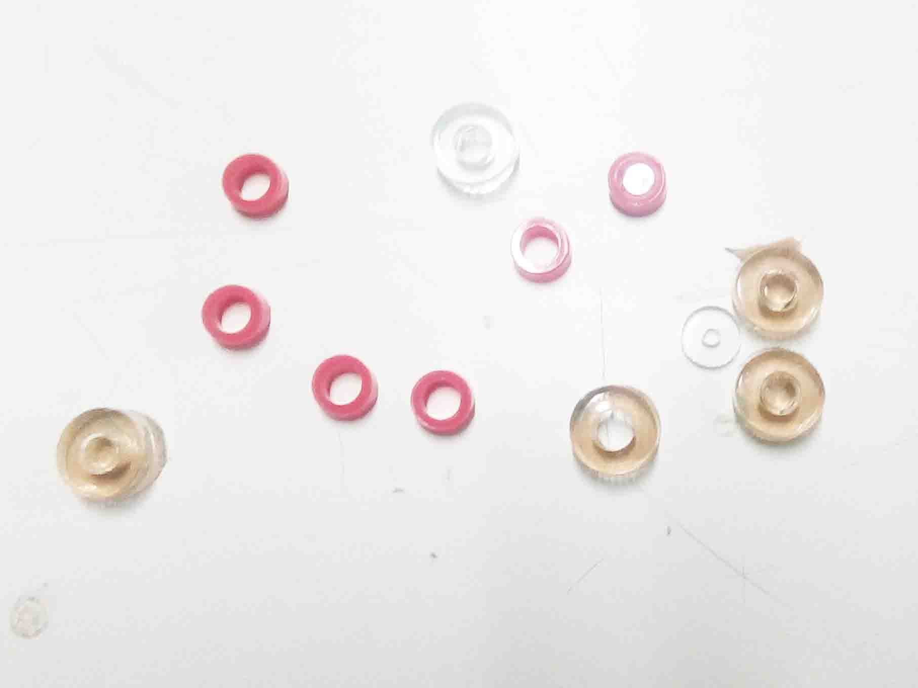
I also cut out some spacers too.
Now I have all the parts I need. Let's start assembling the Mechabeest...
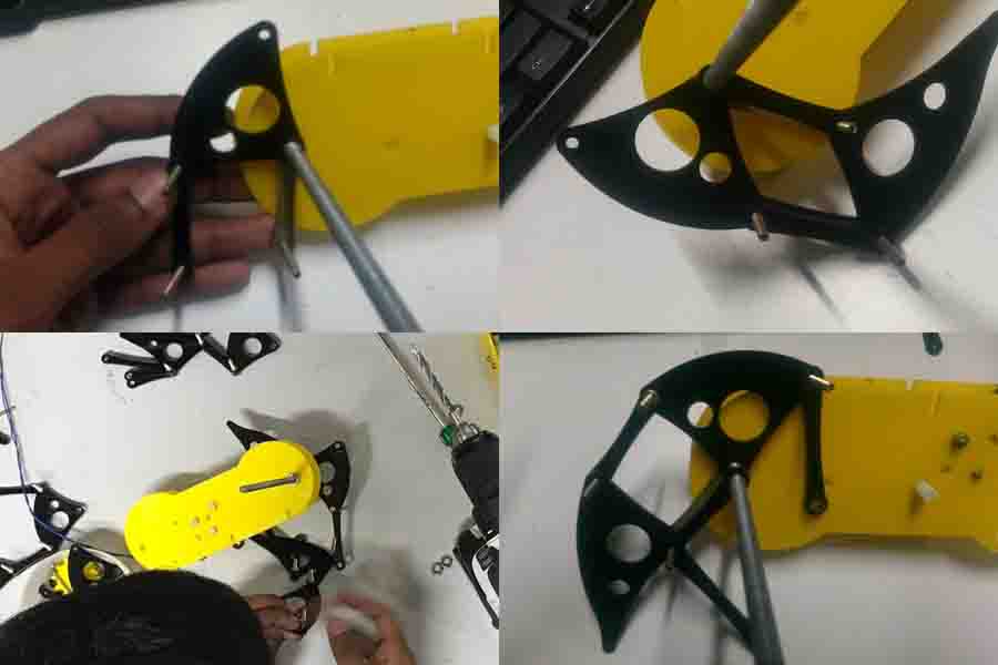
Assembly
So let's start the most fun part. The assembling part.First I need some nuts, bolt also some threaded rodes..
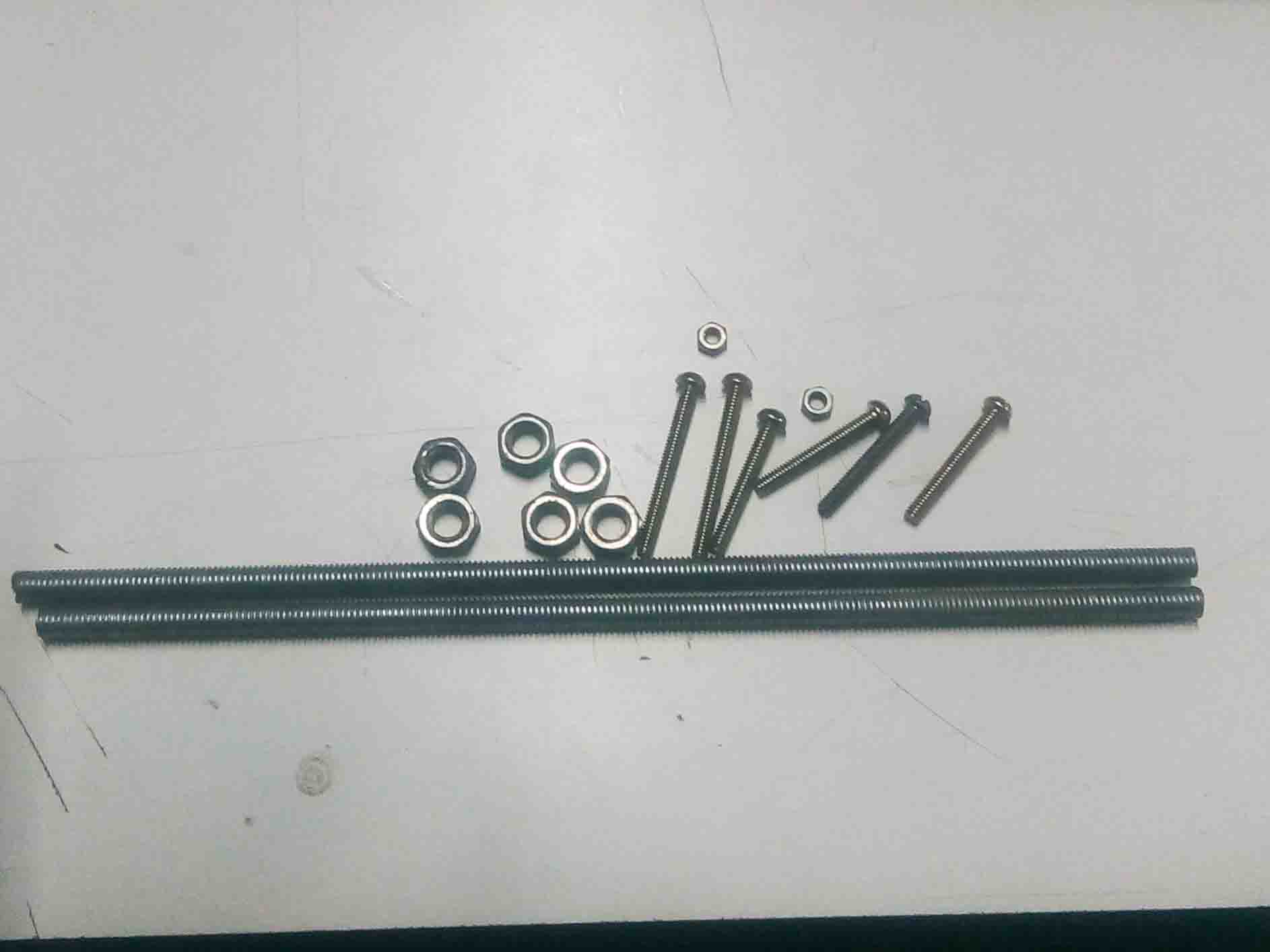
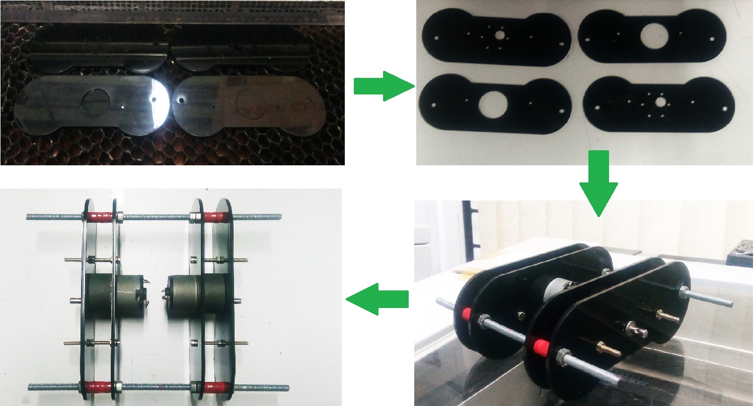
So first assemble the chassis and the bo-motor. For that we need following parts.
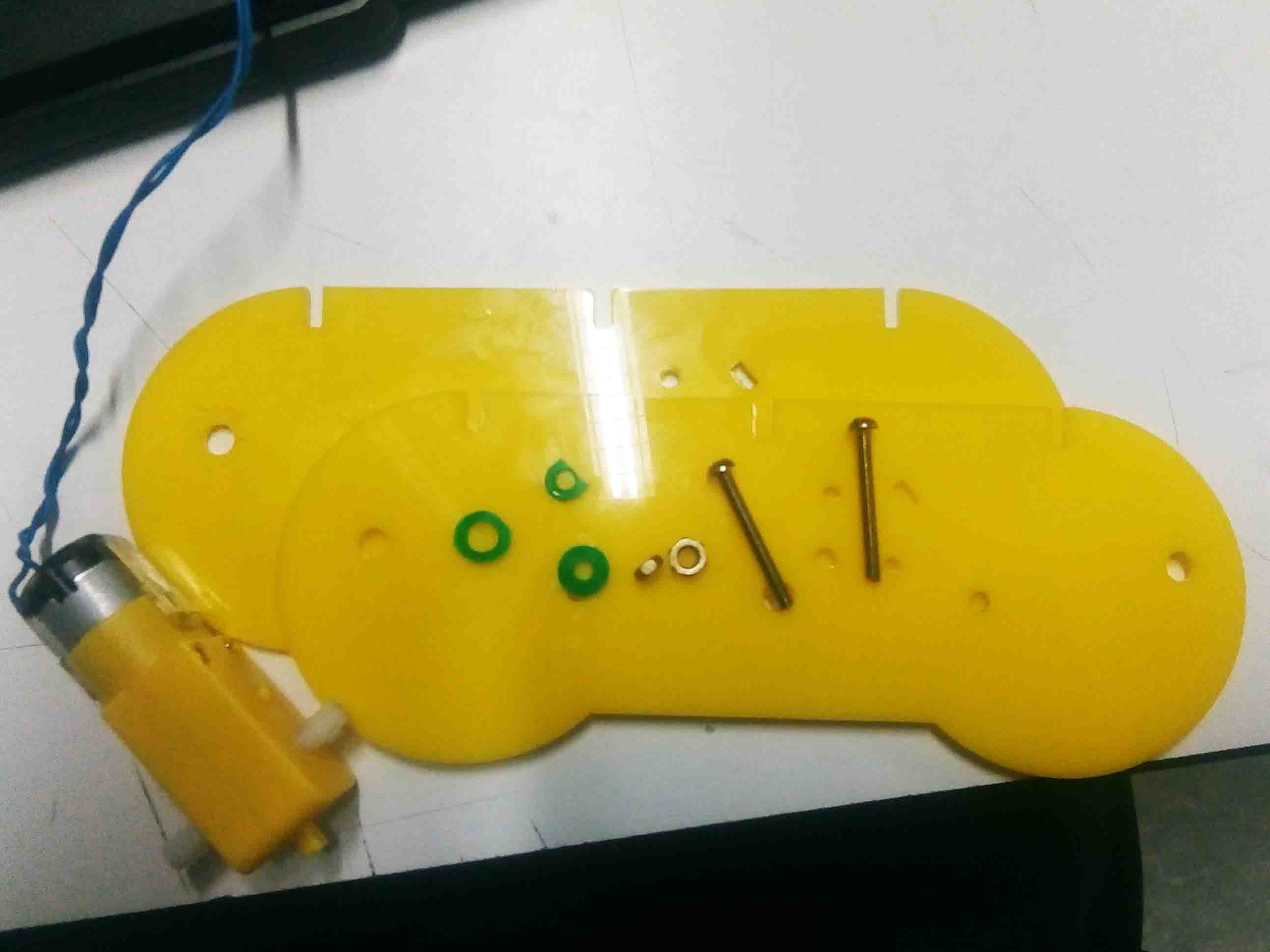
First take the face plate and insert the bolts into the holes. Then place the motor through the bolt and place the second faceplate and tight it with nuts.
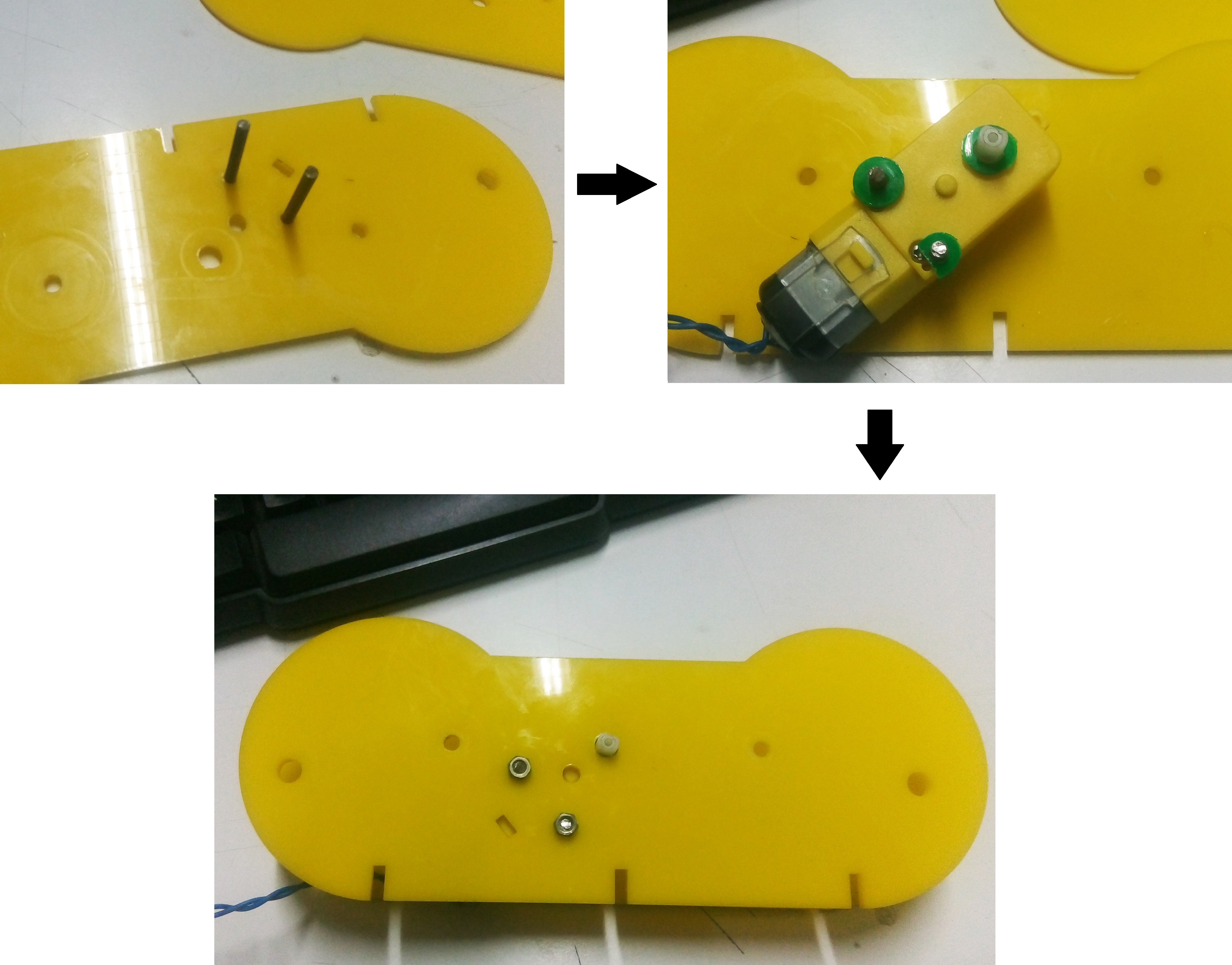
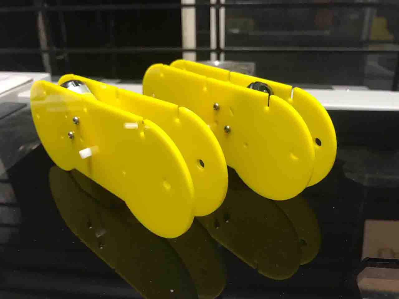
Here is the finished chassis
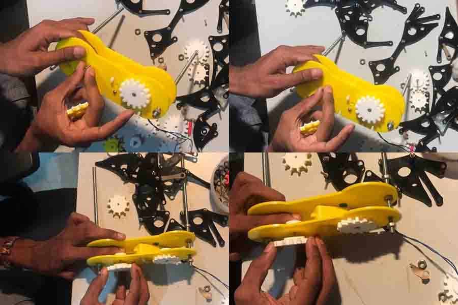
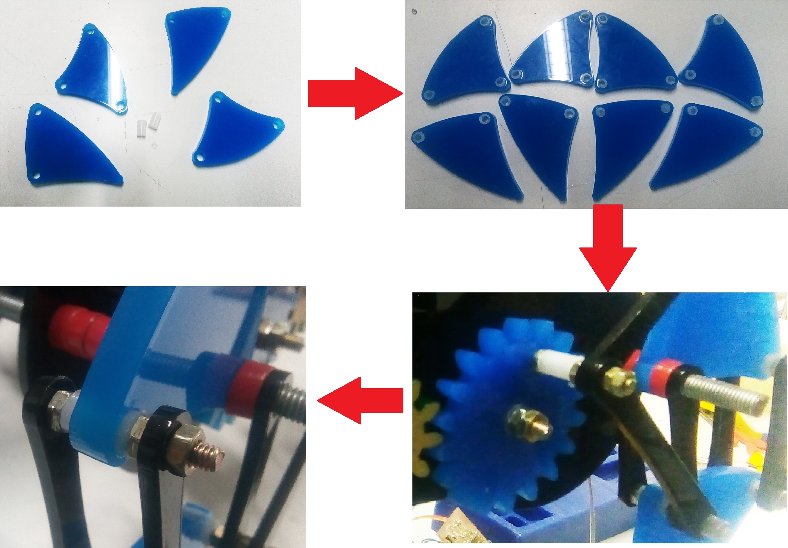
Let's start with gear assembly. Let's begin with drive motor gear that connecting with the bo motor.
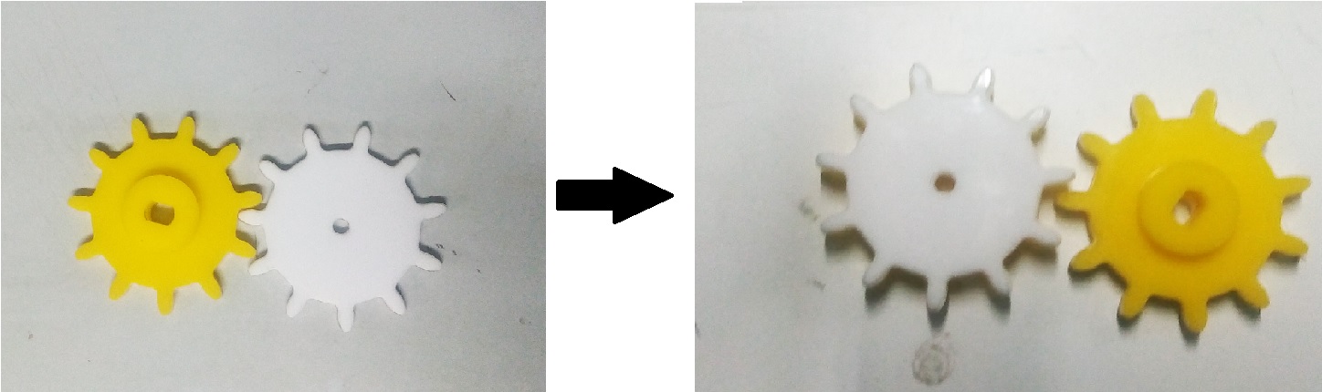
I have applied super glue to joint them to gether. Next the crank gear.
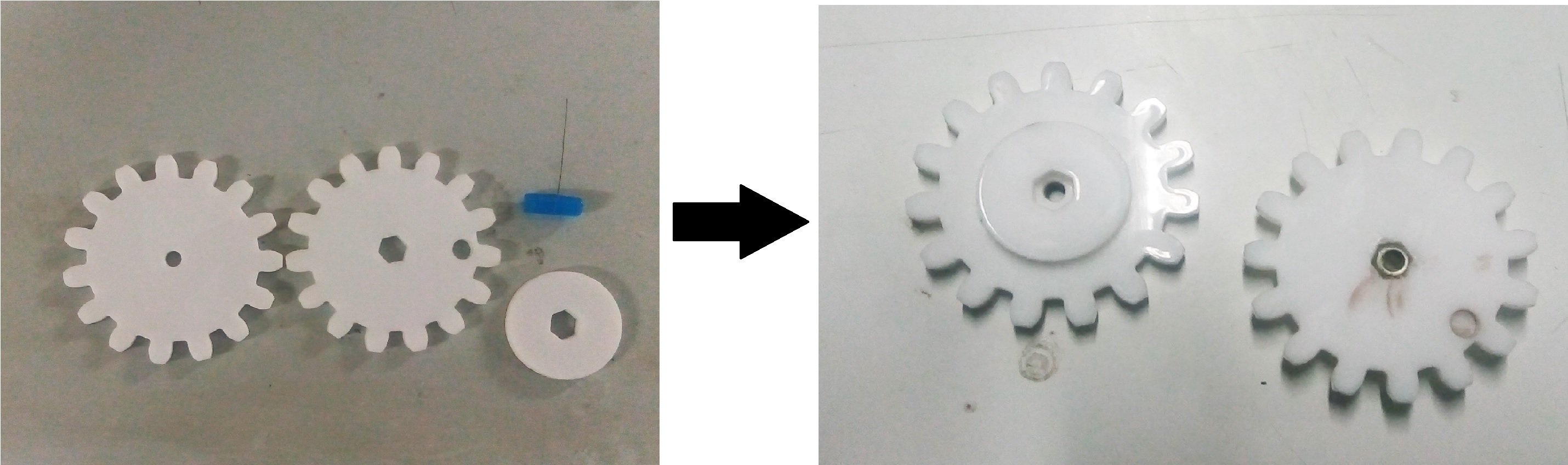
I have repeated the same process for the shaft connector which connect gears woth the chassis.
I have used glue to join them to together
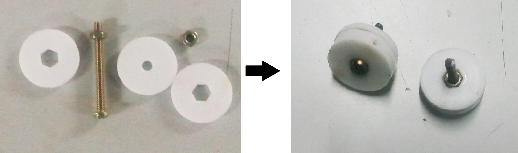
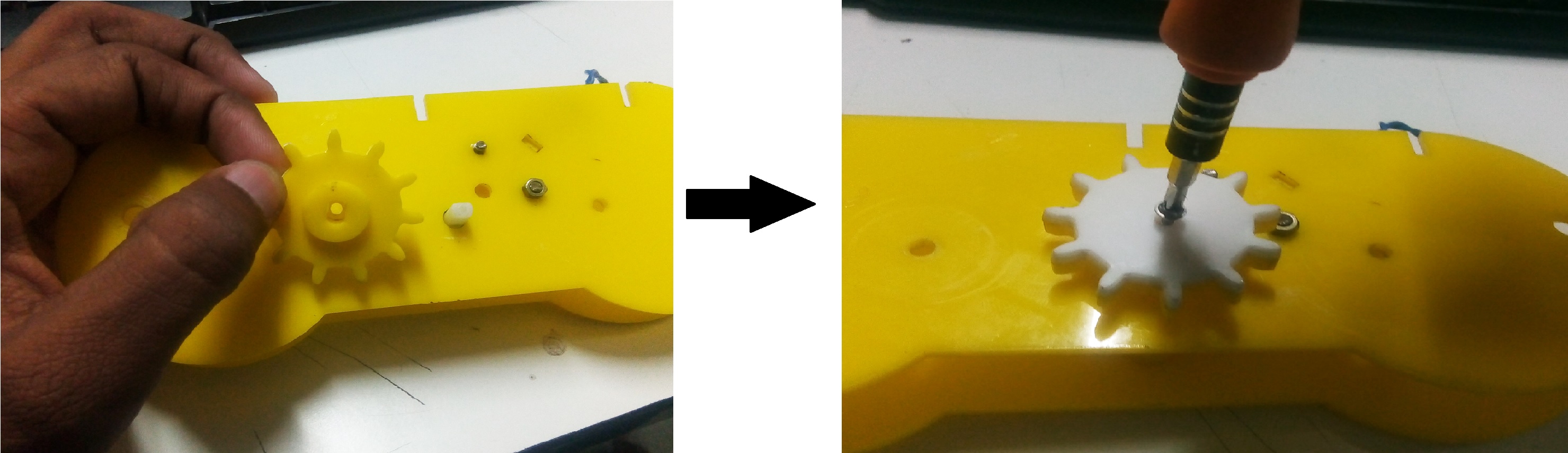
Now I can connect these to gether. Let's start with the drive gear. First place the gear on the bo-motor and screw it down.
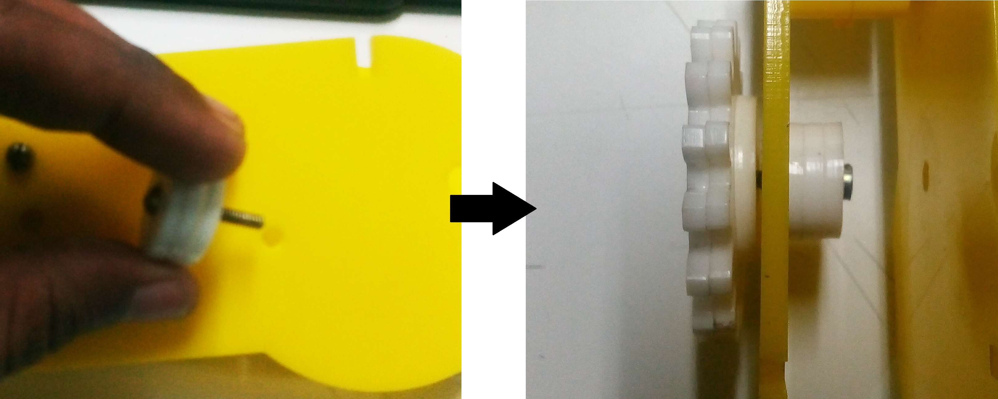
The take the connector shaft and place from the inside ofthe chassis. Place some nuts inside the slots of the crank gear and screw twist it in.
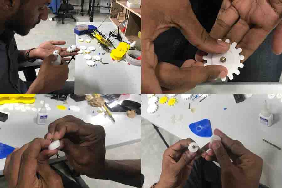
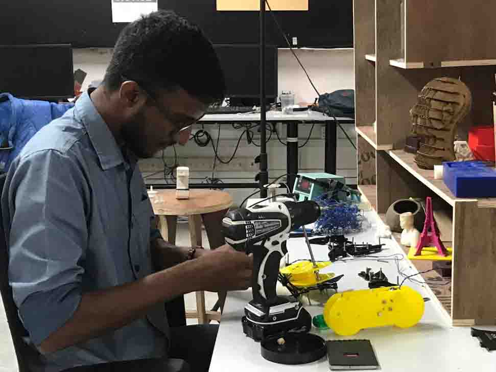
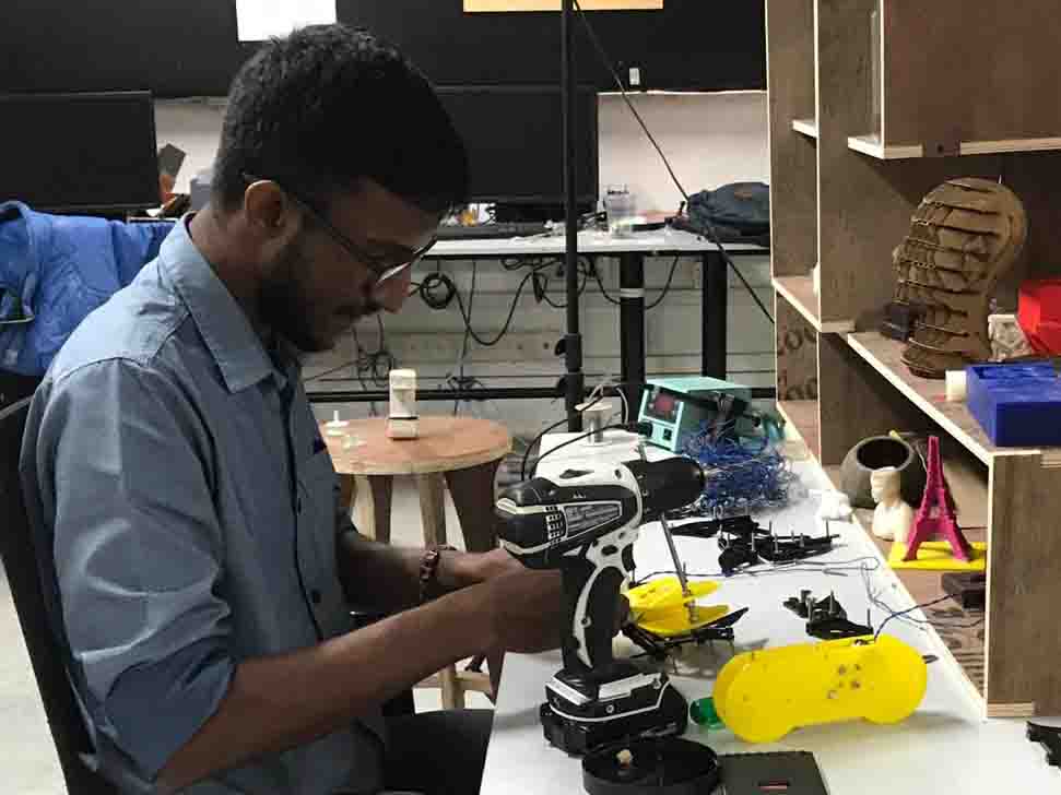
I tried to minimixe errors while assembly.
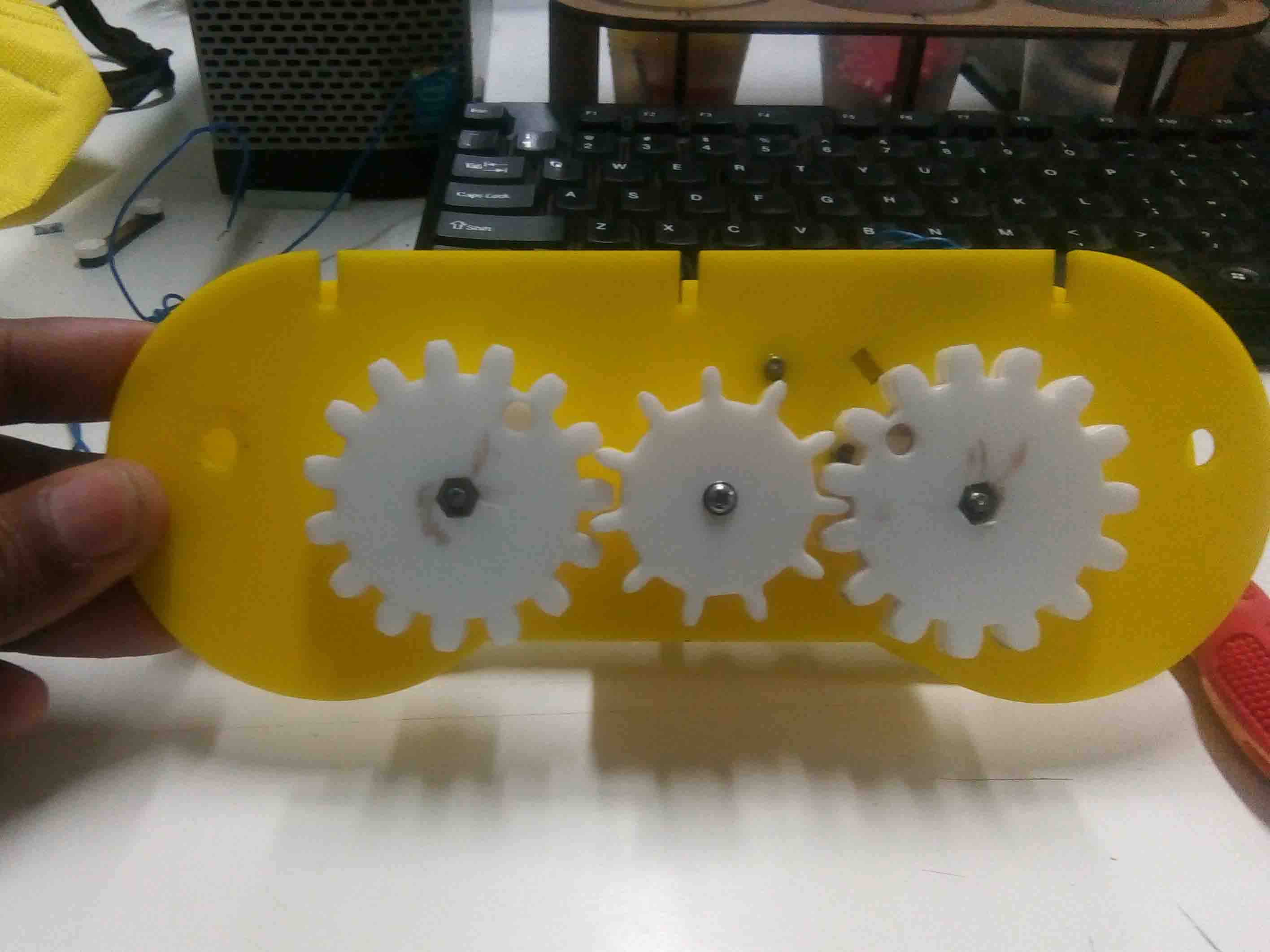
Here is a finished assembly of the gear mechanism.
Here a working video..
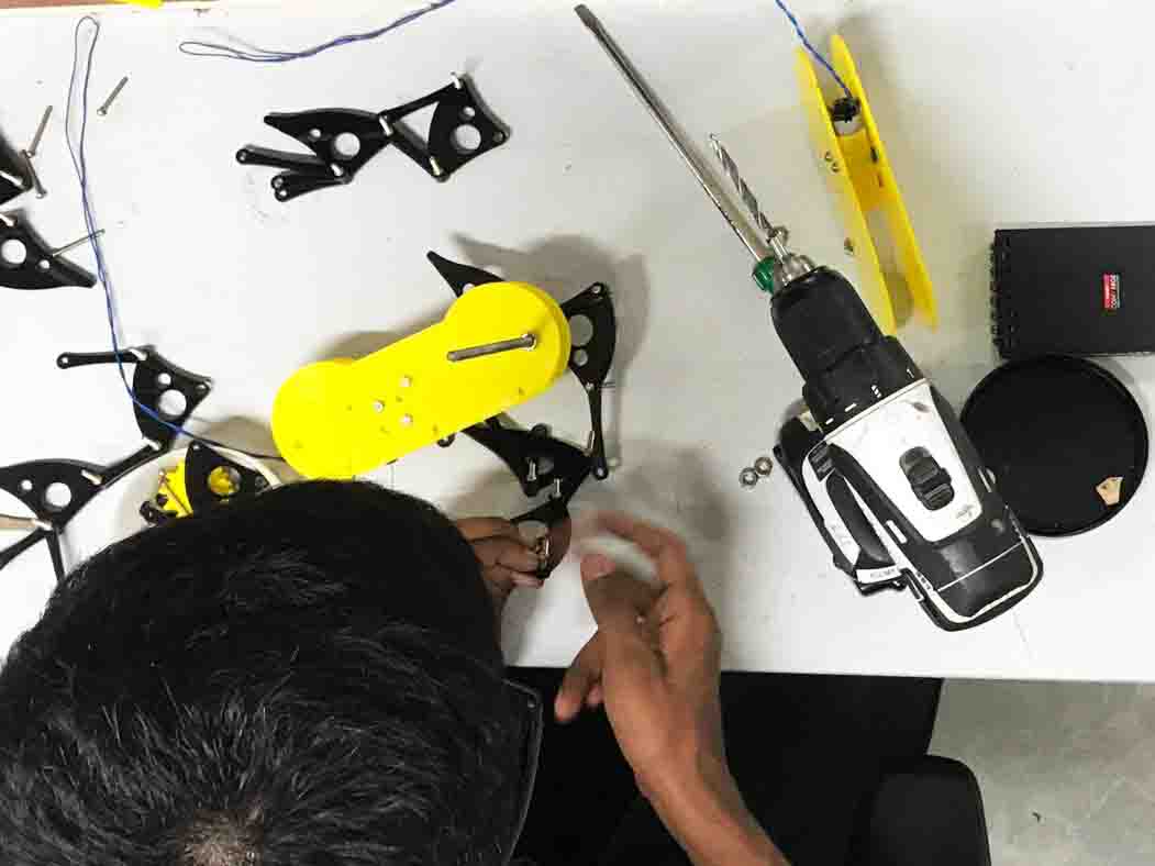
Now let's assemble the legs. For that I have already cut the parts using laser cutter. First place the parts accoring to the design above and tight it down using screws.
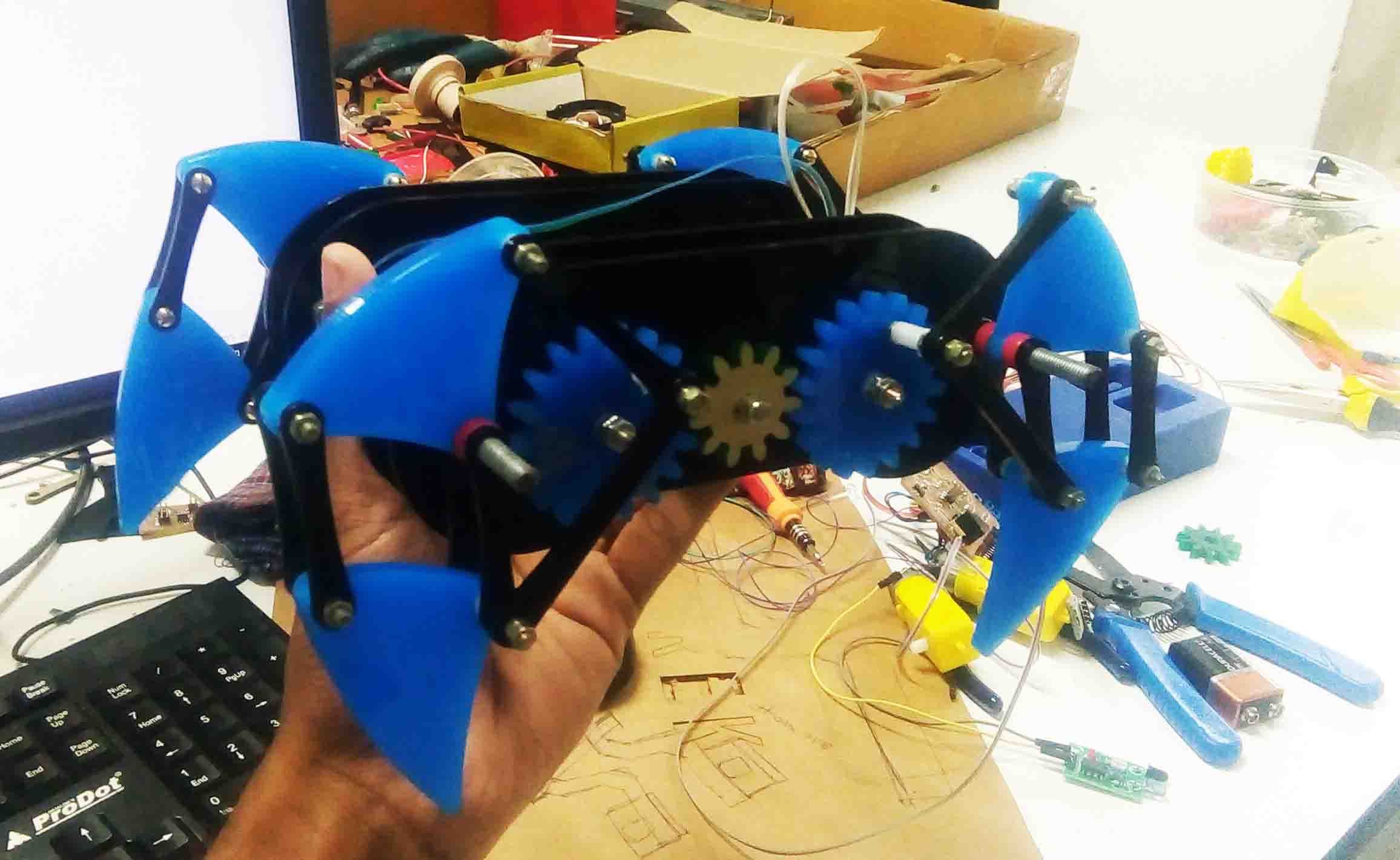
Here is a finished test video of the mechanism full connected with the motor gear drive with the legs..
So lets connect the rest of the body parts and see what wanna do...
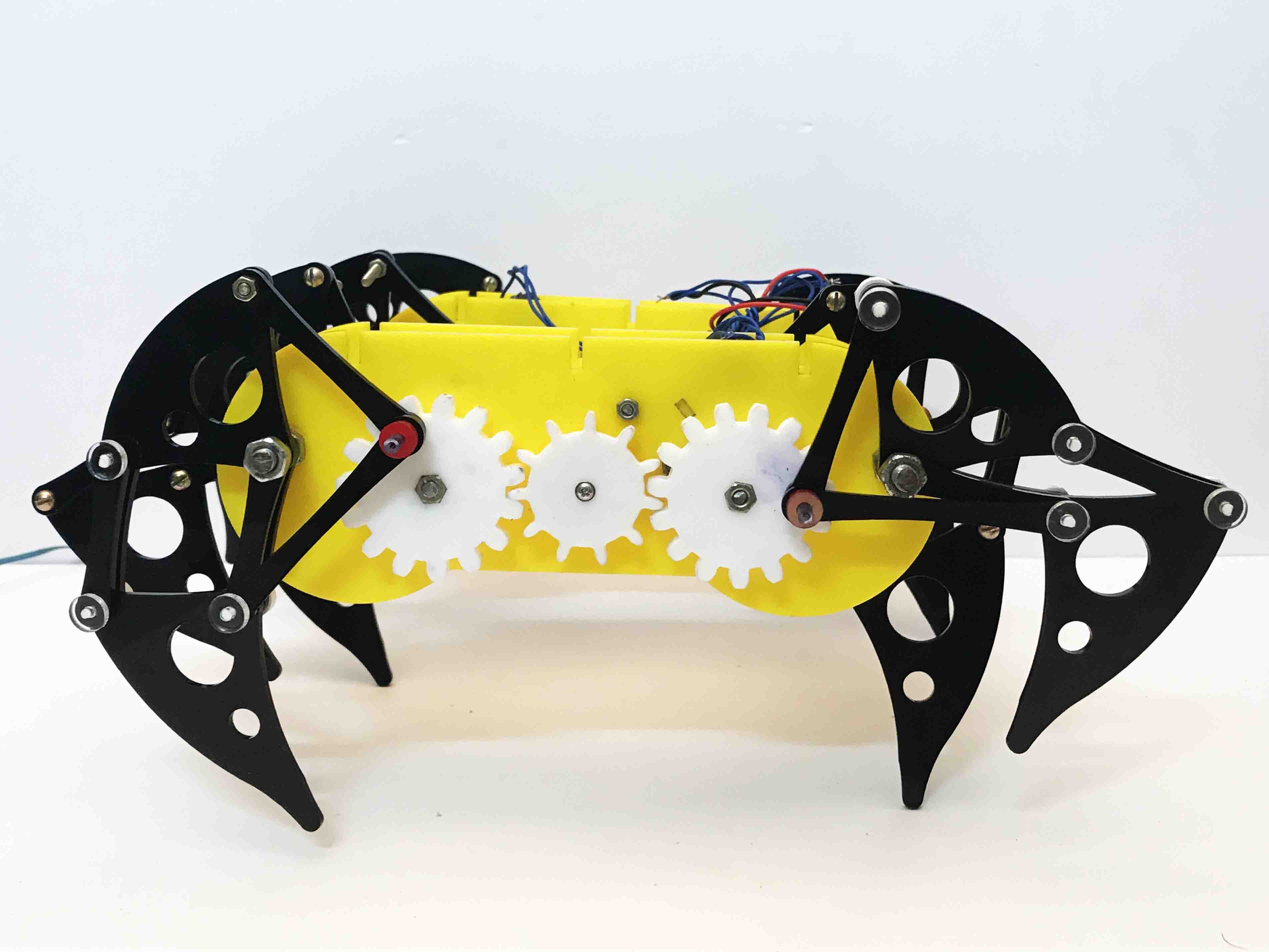
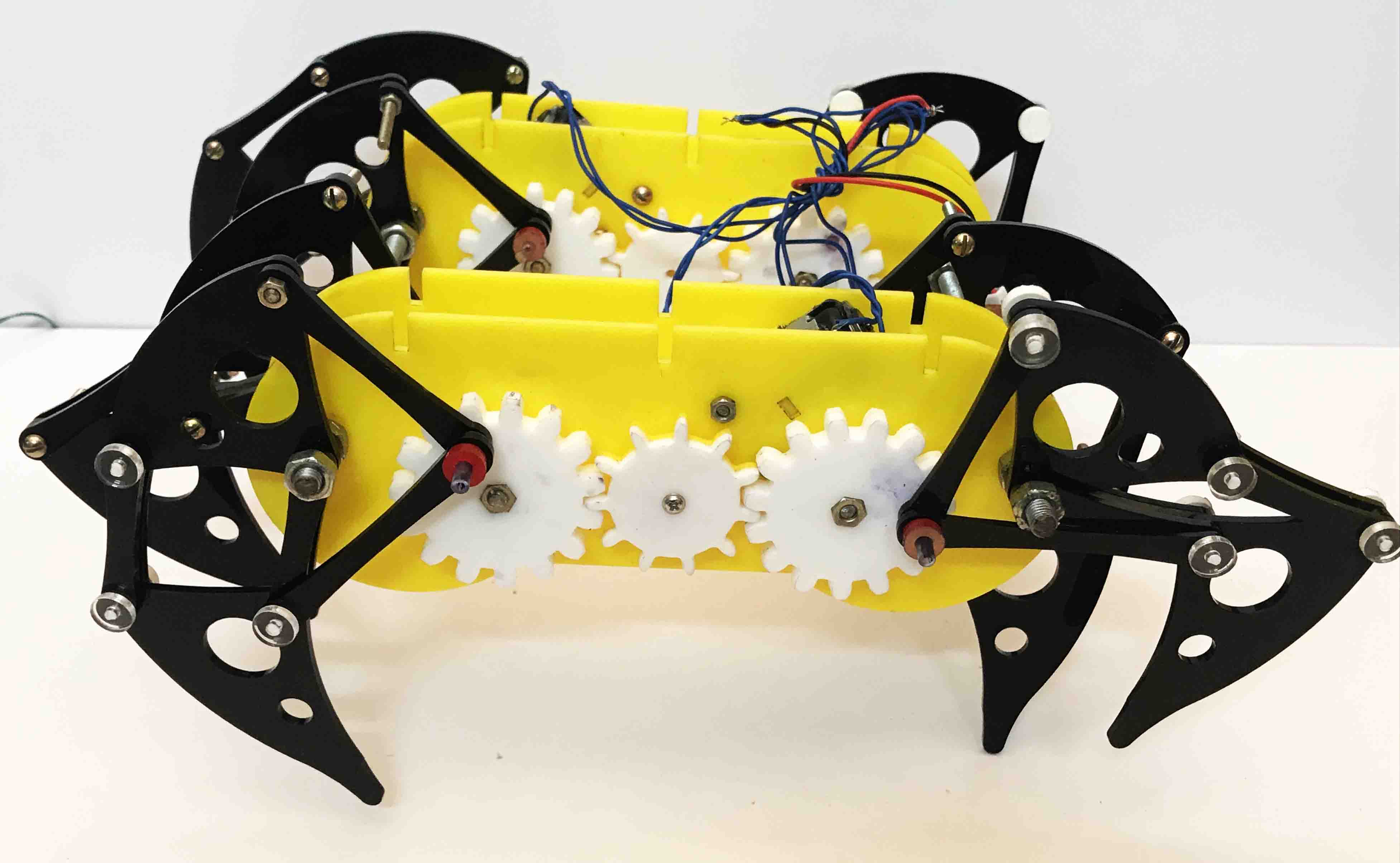
Here is the finished Mechanism..
Electronics Production
The mechanical part assembly is done for now. Now the electronics parts are needed to be designed and producesed. So let's start with the designing part. Here I am going to use EagleCAD software. First just list out the components we requires...
Now I have the components listed. So let's start designing. First opeen the EagleCAD software. I started from the basic circuit with connection to L298N Motor Driver.
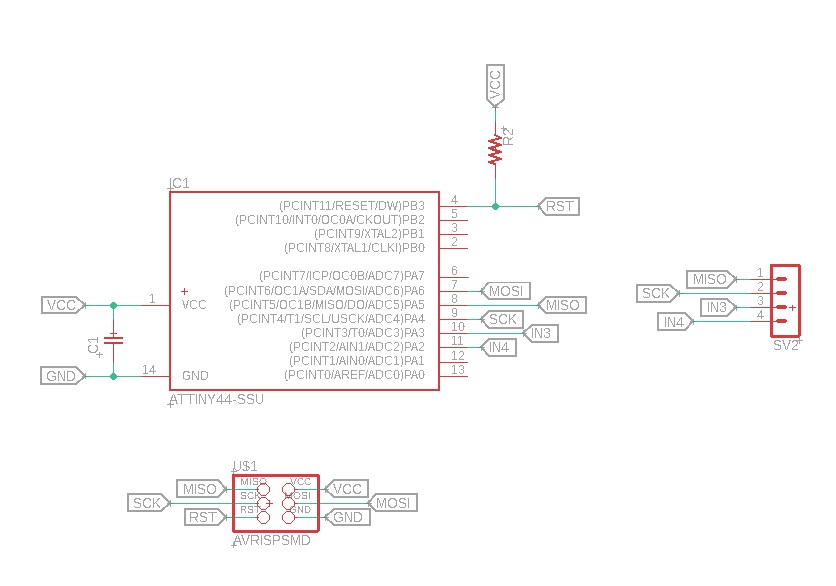
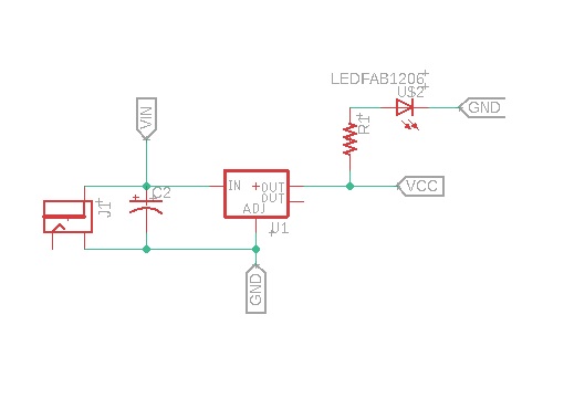
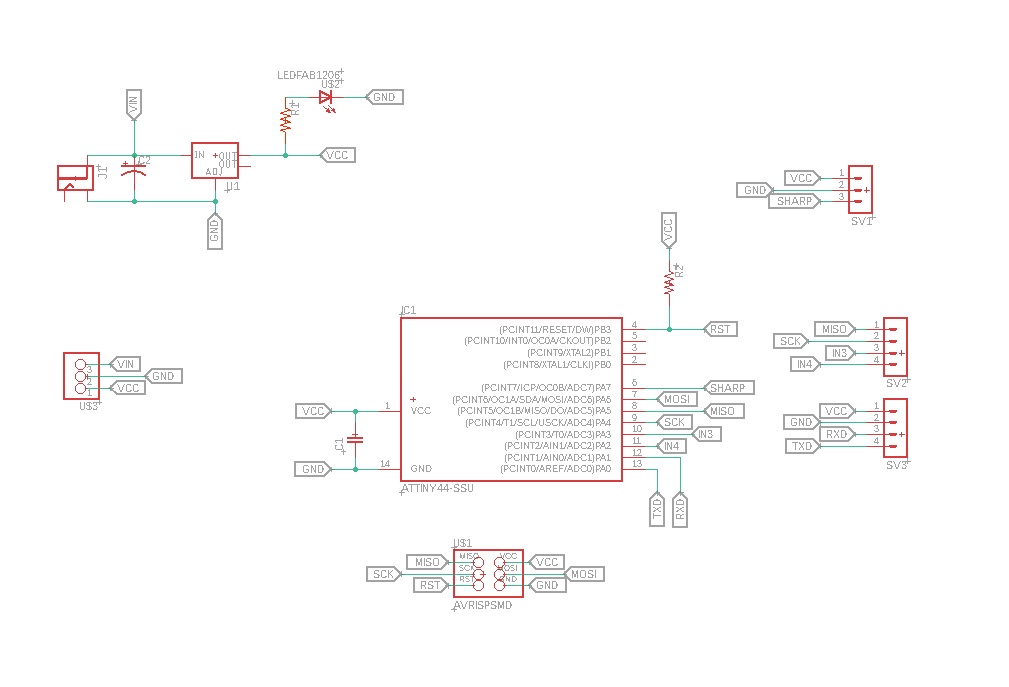
The circuit need power to work properly. Here I need power for both Motor driver as well as the microcontroller. So I have selected LM1117 voltage regulator to supply the power required.
I also add bluetooth module and a SHARP sensor to the board so that the Mechabeest can control using bluetooth and also run autonomous.
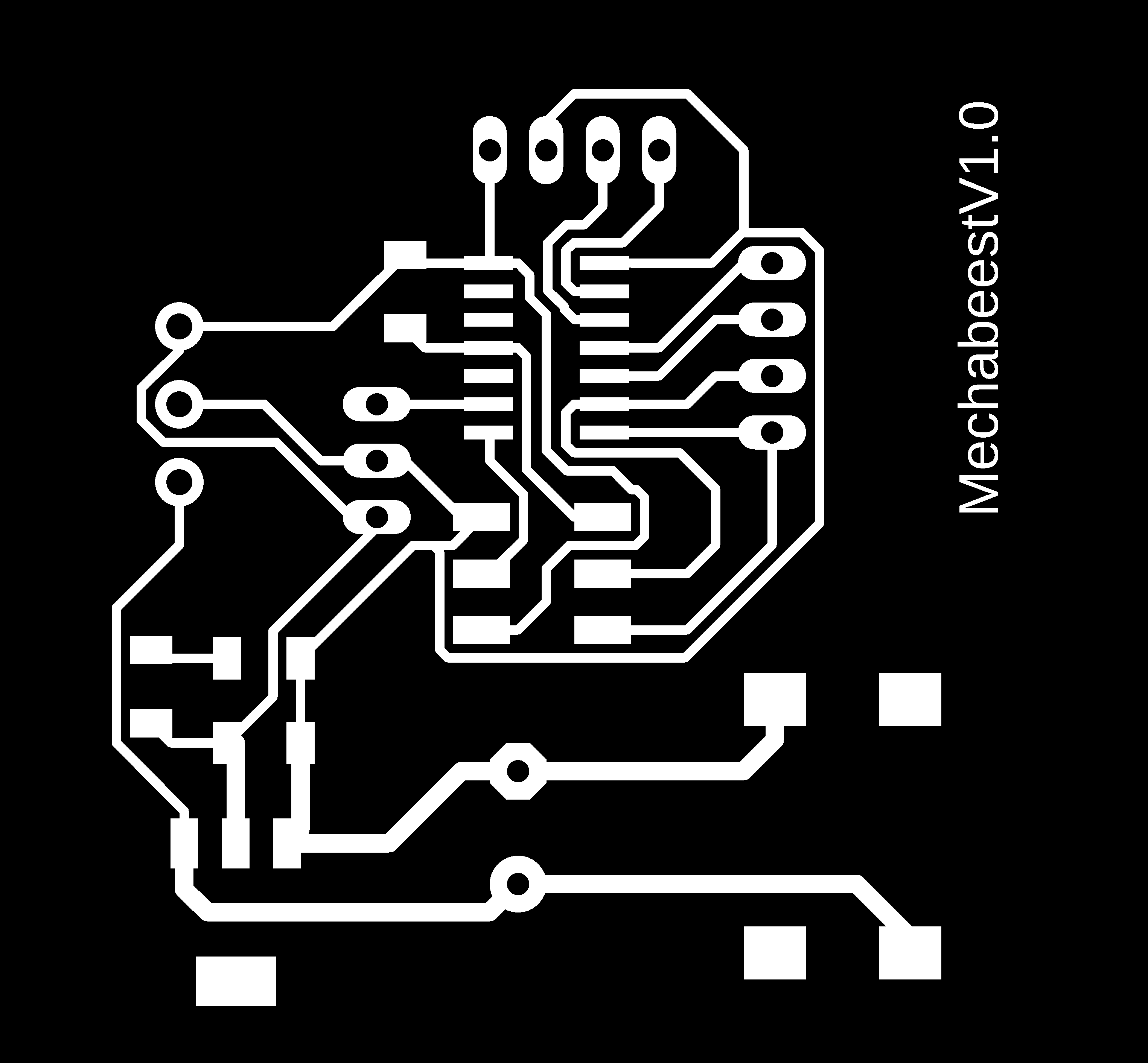
Turing the schematics into board is the next task. as I did in previous weeks, I switch to board view
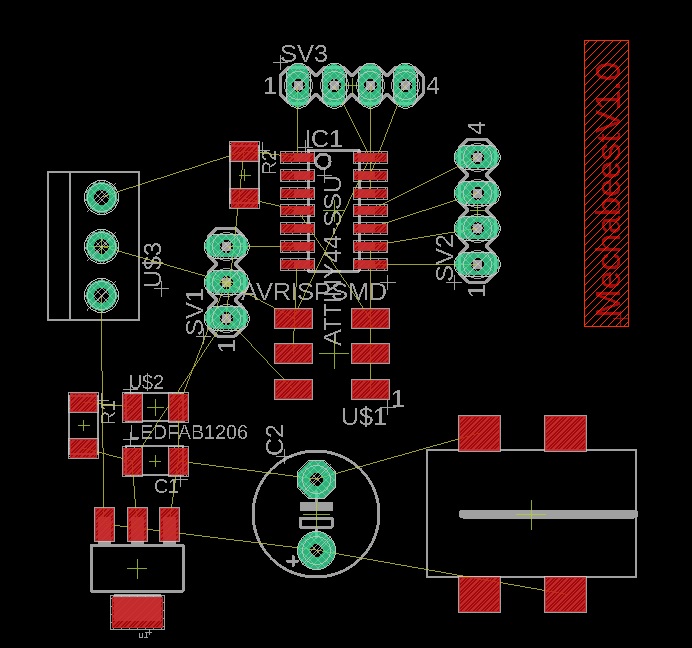
First I route the power lines. Input power can be vary from 6-30V. So the lines thickness should be larger than the signals. I have given 32mil for the power lines here.
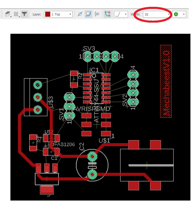
Power lines are finished. Now I have to route the rest of the lines. For signal lines, I am using 16mil
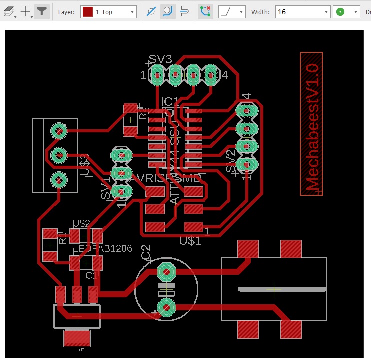
I didn't use "Auto-router" function here. manual routing was enough here. Also no vias has come during the routing. For the final touch, added a dimension box for cutting
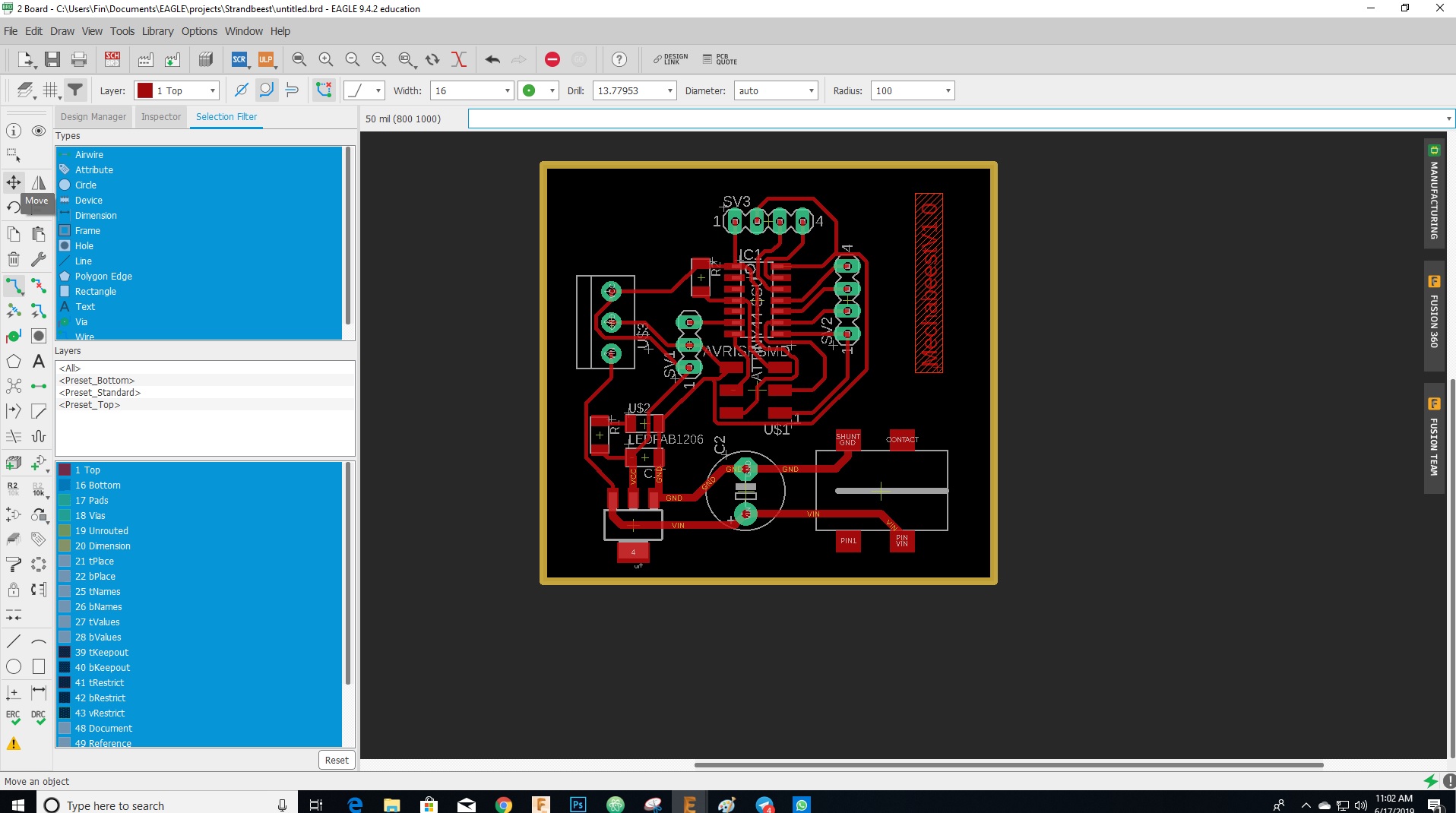
The png image should expored out for PCB Production.I have exported 3 files. they are given below..

You can download the files from Here
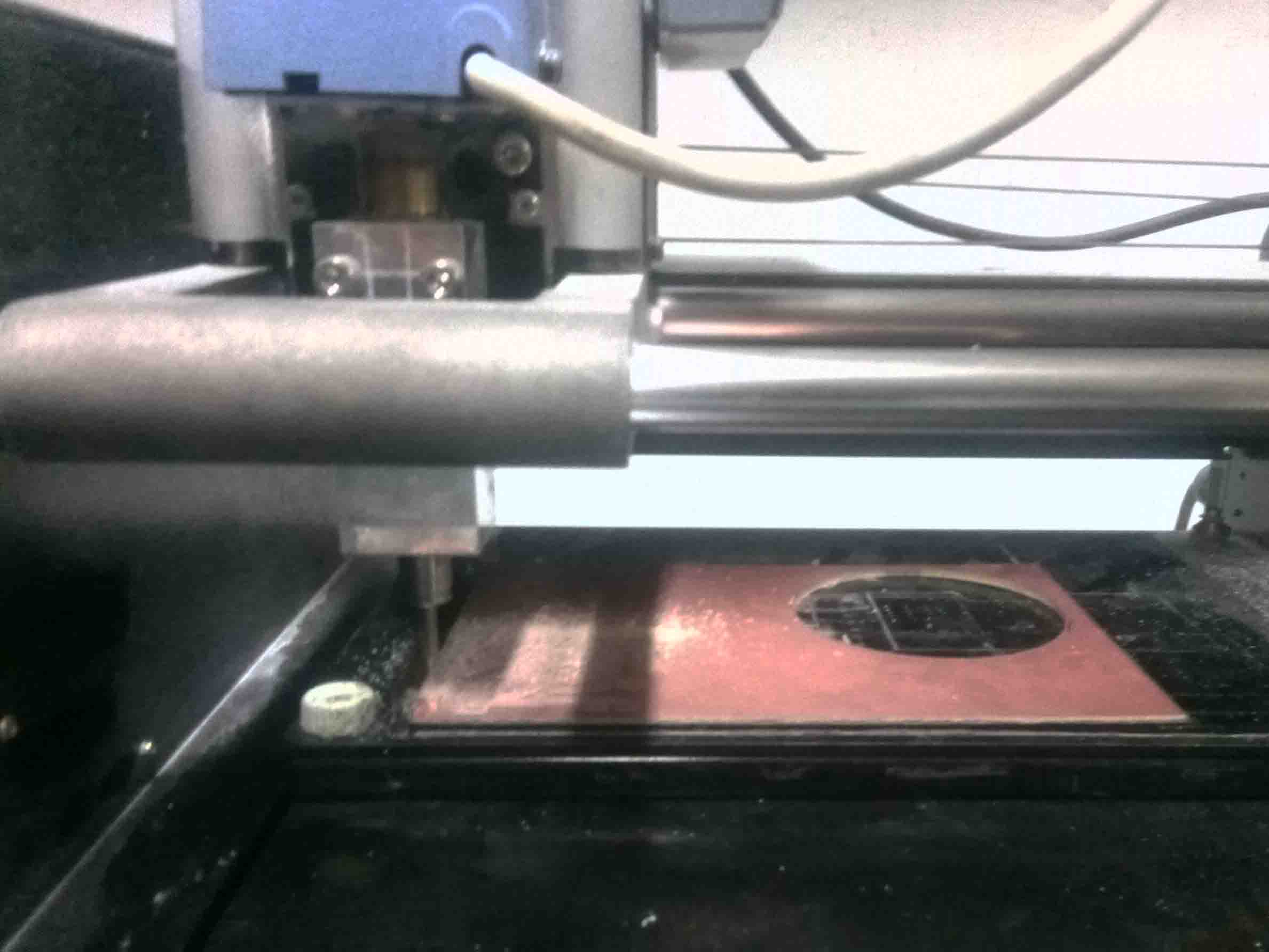
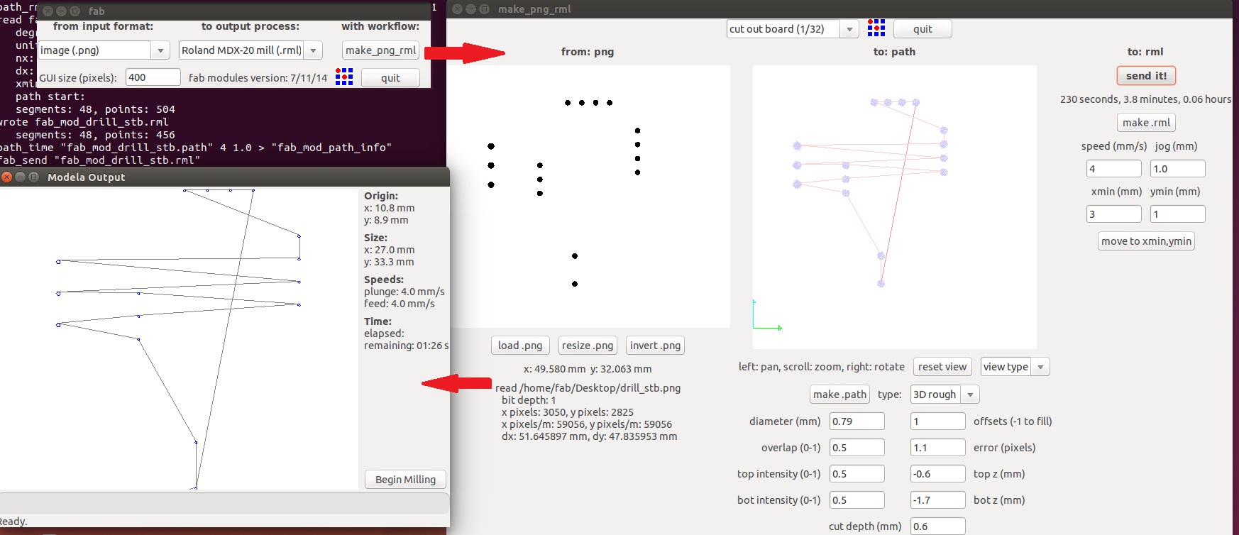
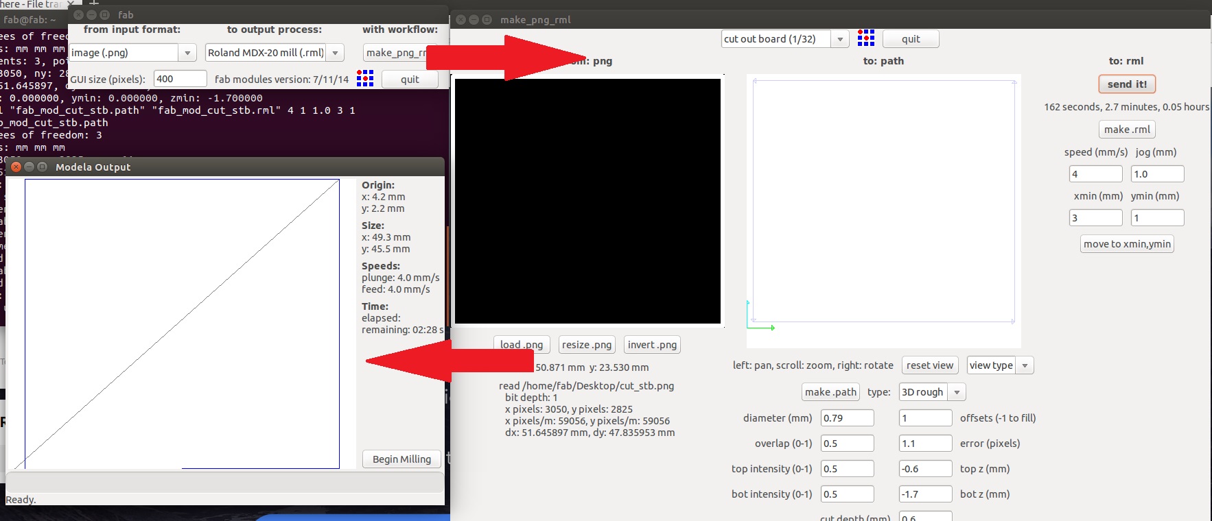
.Now we can mill the board using Modella CNC router. For that first change milling bit. here I am using a 1/64 inch milling bit. So goto fab modes and set for milling
And start milling the traces
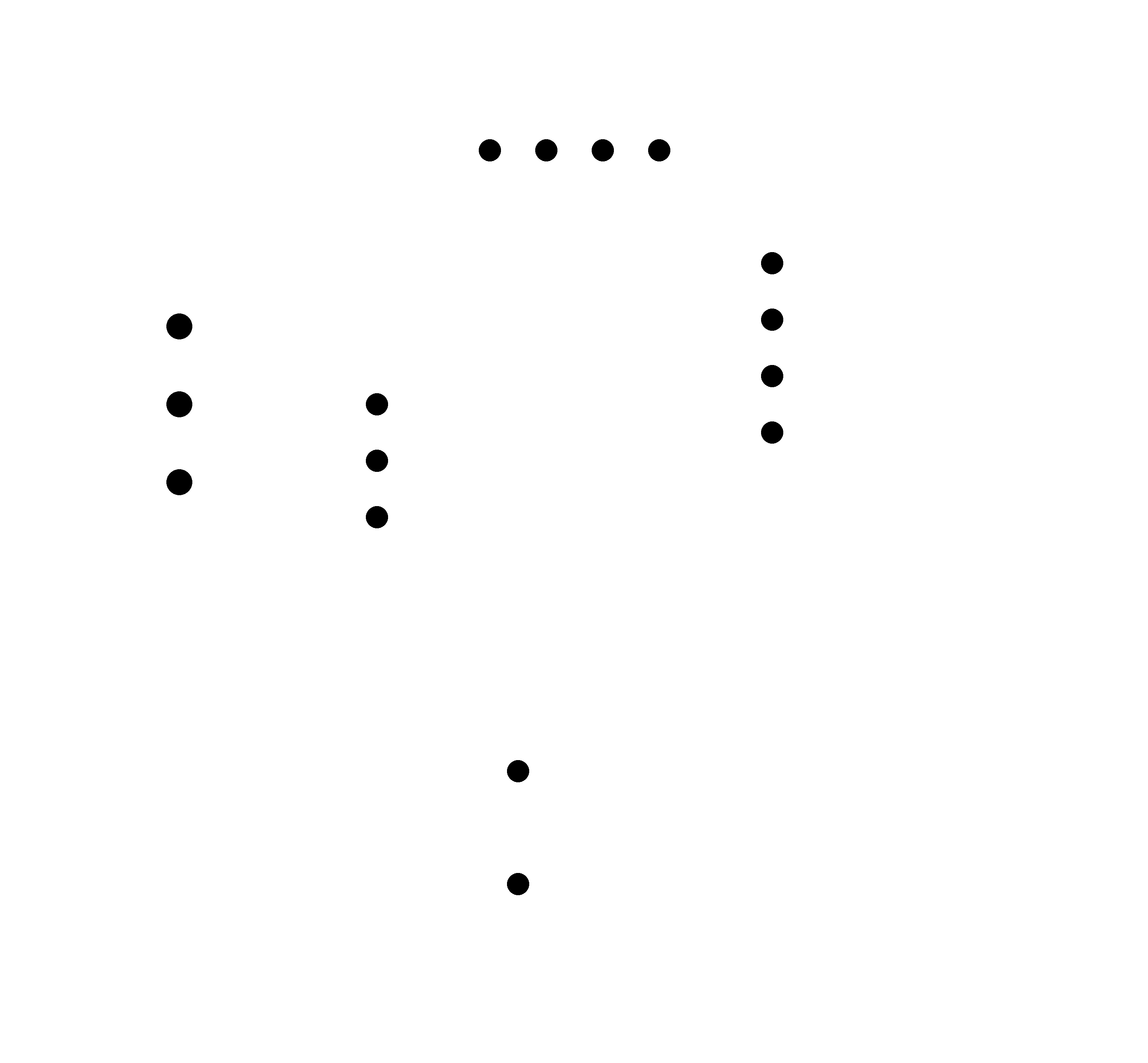
Now change the bit to 1/32 inch cutting bit. Set up fab modes for cutting and load the drill holes png
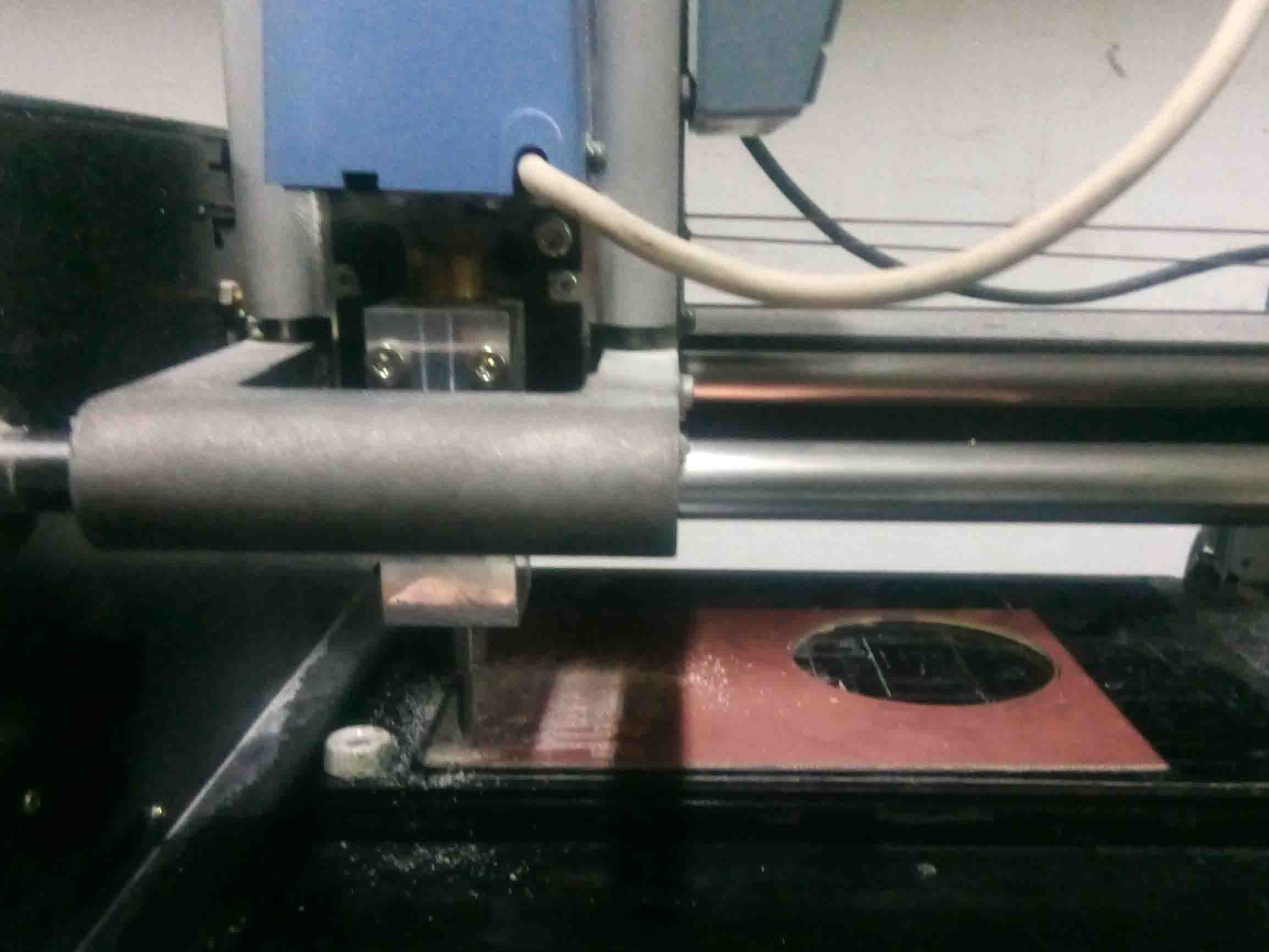
Holes are in place. All that left is to cut the board out from the large PCB. Load the cut file
And start milling...
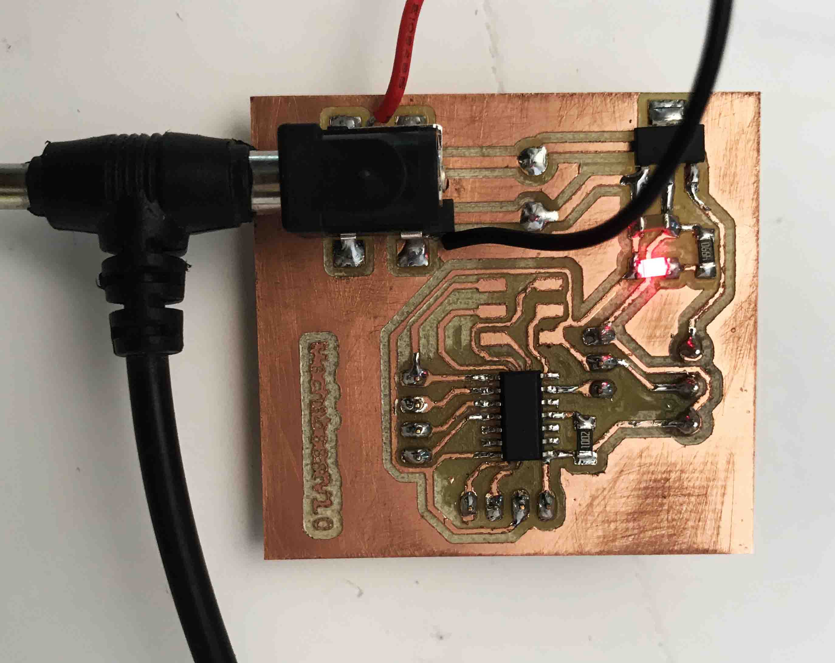
I got a nice finished board. Now I have to solder with the components thats collected at the beginning
Here is the finished board Assembly
Let's pick the other boards as well
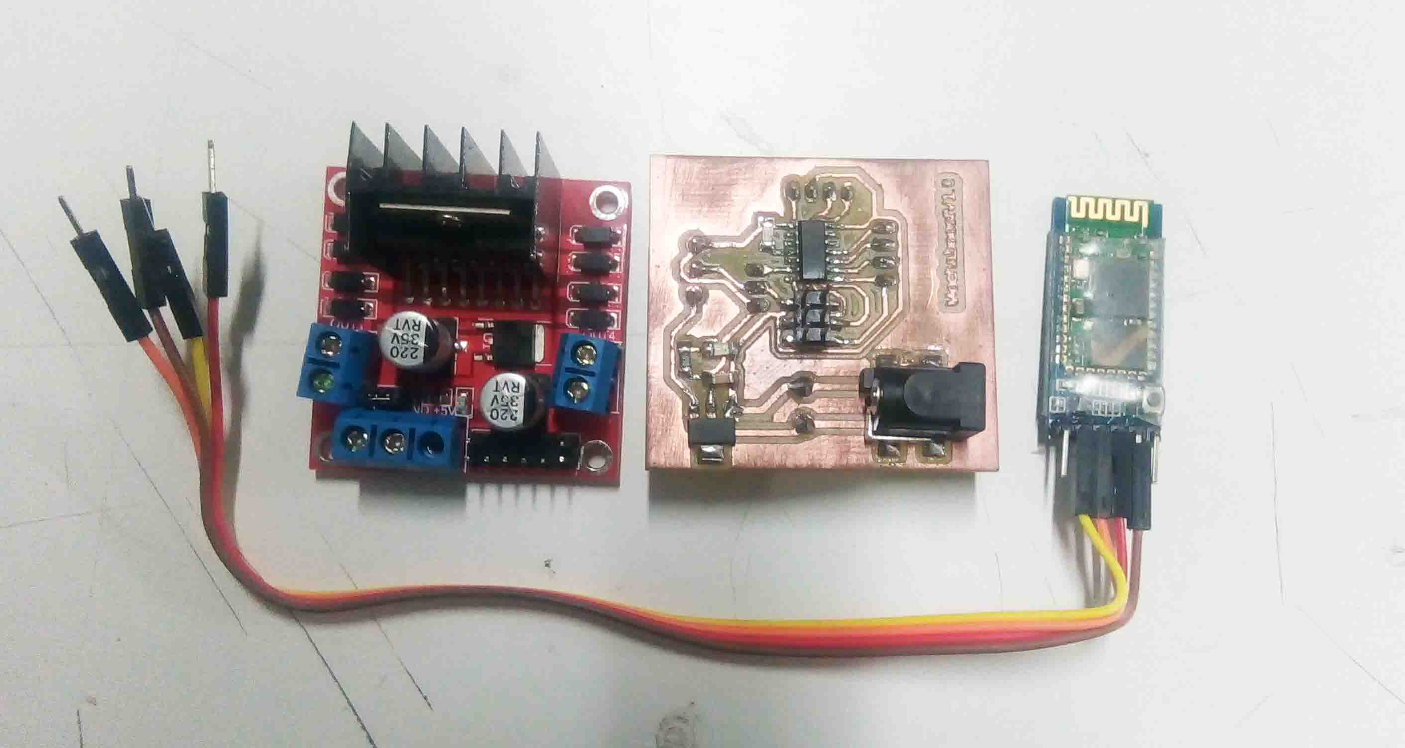
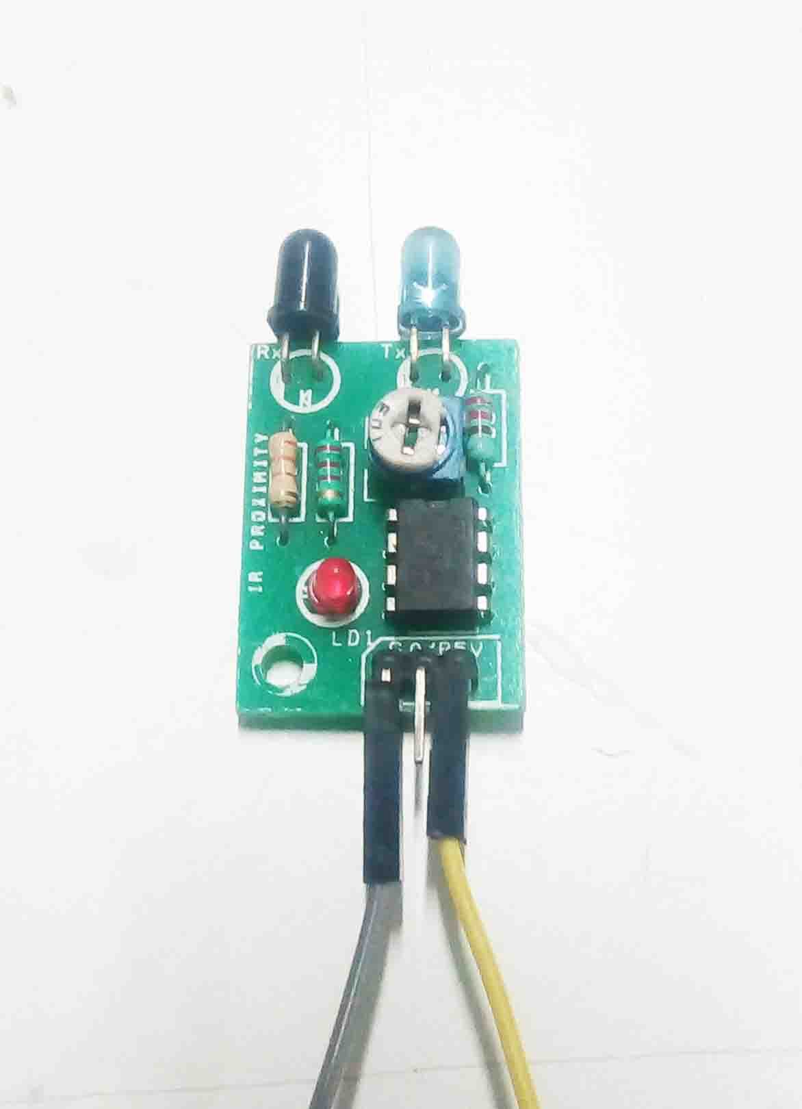
IR sensor
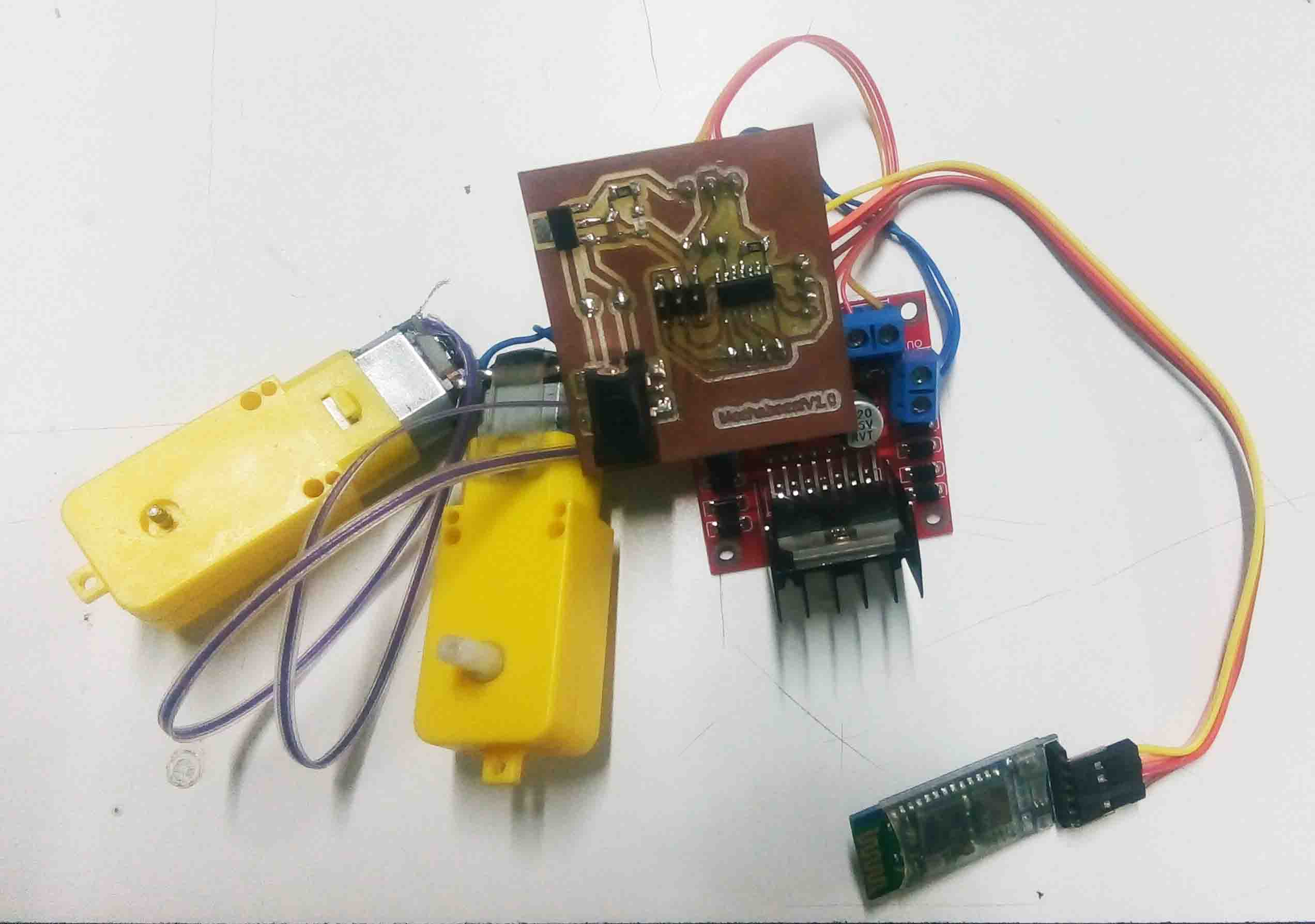
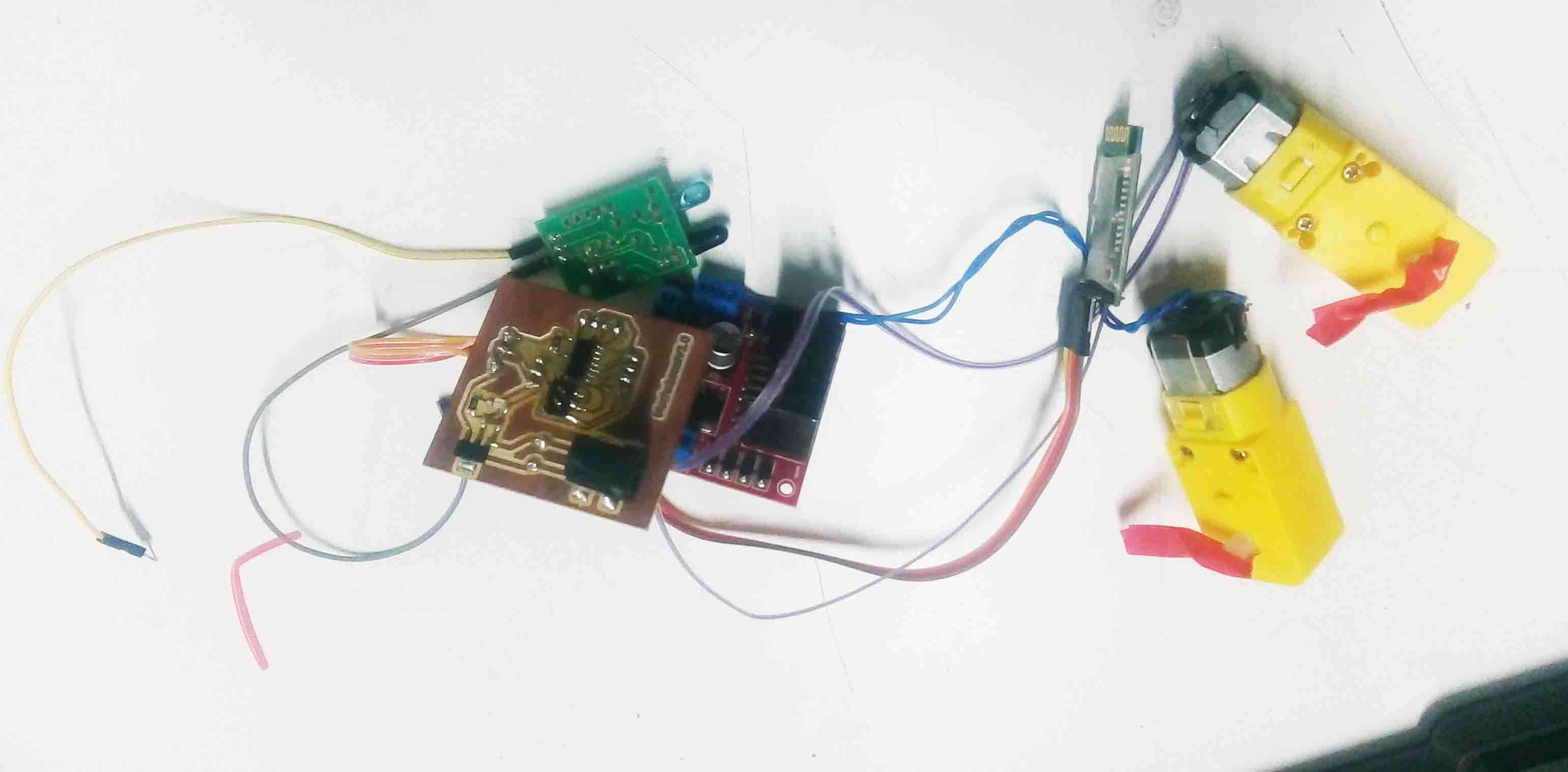
Let's put everything to gether and look
Now we need is an Android application to control the Mechabeest. So let's build an app...
Android Interface
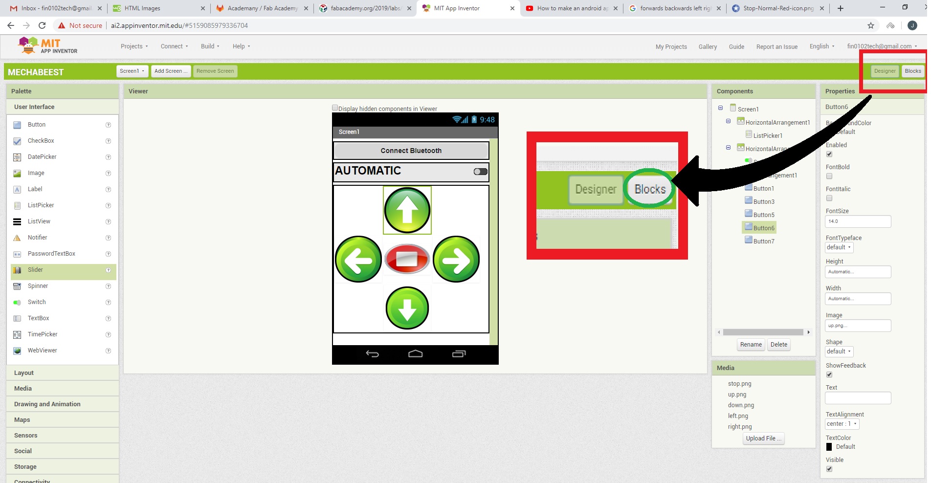
So for building an android application, i am going to use "MIT App Inventor". It's a simple way to make apps. So I started with creating a new account because I for geot amy old mail ID. The things I need the app to are listed below..
So let's begin. Start with the layout option. Insert horizontal Arrangement 3 times and click their width to parent size. Also add table Arrangement and put raws and column 3. Add buttons like below
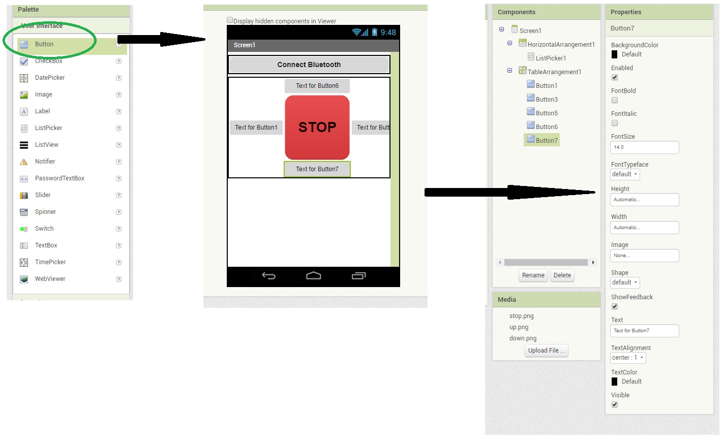
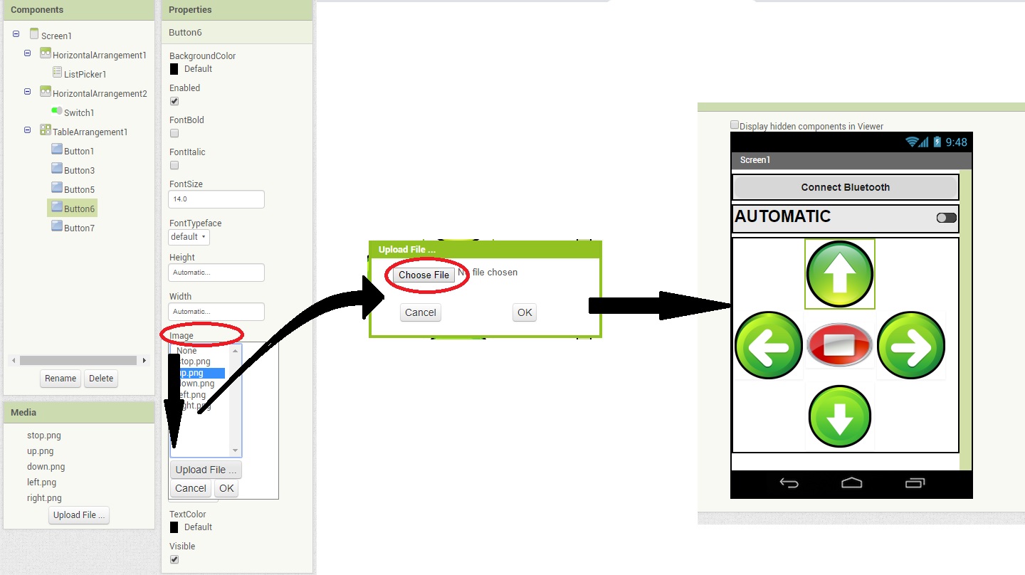
I need to show the direction to the button is pointing. So I add Arrow icon to the buttons using image function
Now all the front end of the app is completed. Now for te back end, click "Blocks" at the right top corner of the window.
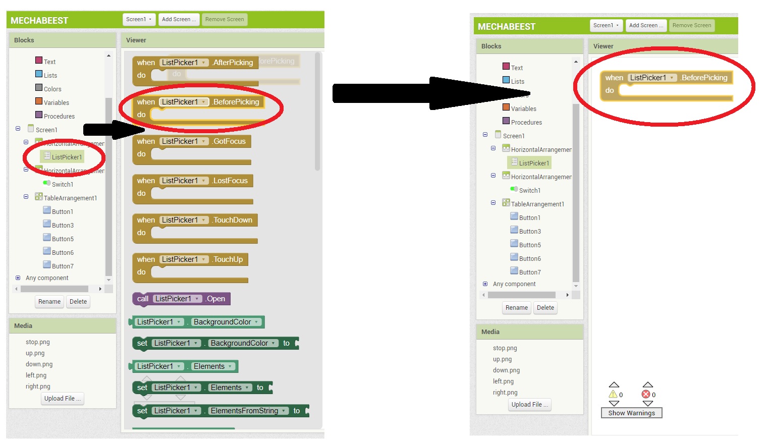
select list picker and select before and after picking tp the pallet
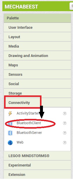
I need to add bluetooth connectivity to the app. For that, I simply go back to design and add "Bluetooth Client" from " Connectivity"
Now I place the blocks like below to establish connection with bluetooth
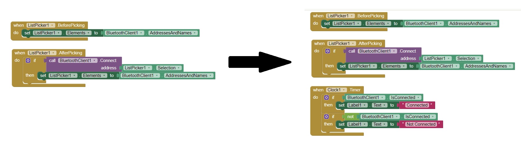
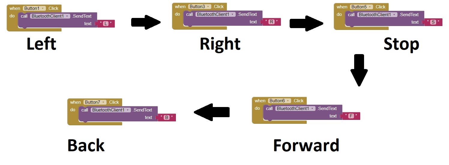
I have also add a clock in design for notification. Now for the controls, pull out each button and put the blocks like below.
Now the app is all done. Now it need to be saved as .apk format. Click save as apk from build options.
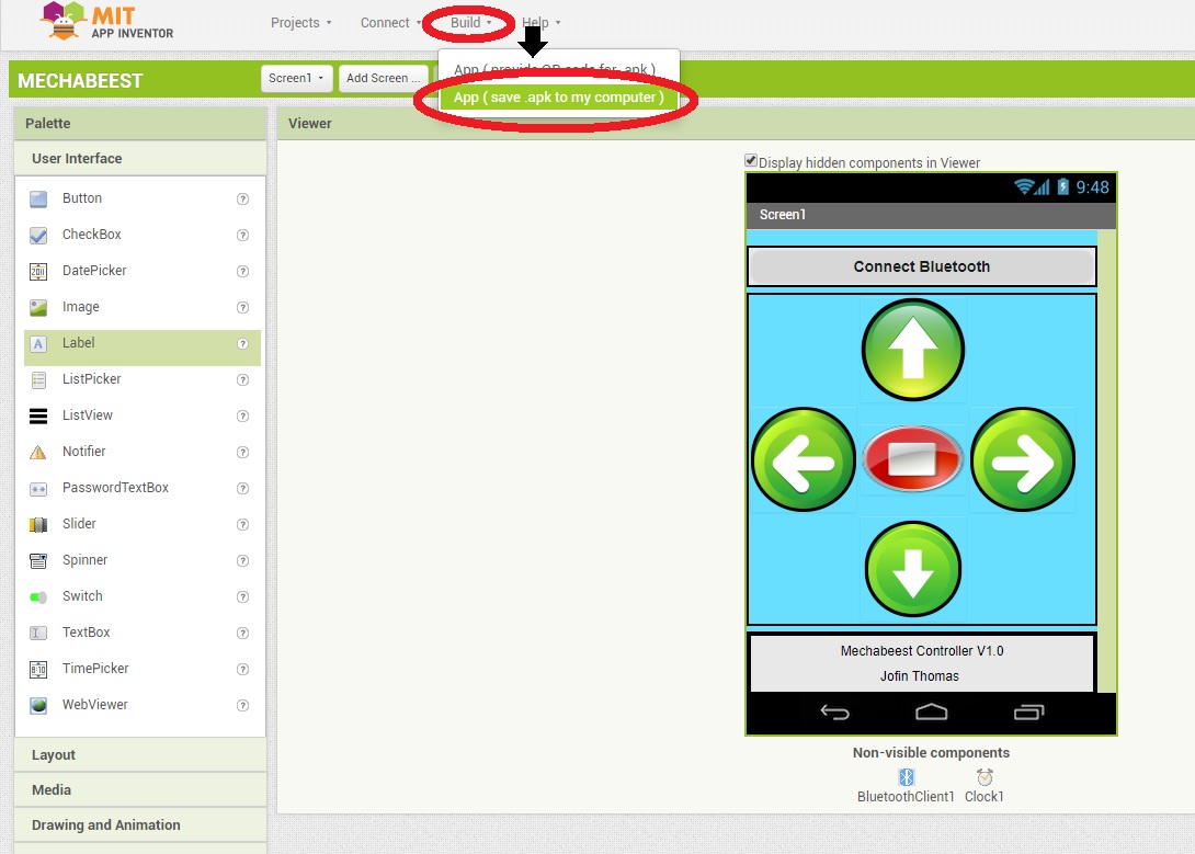
You can download the app from Here.
Embedded Programming
So all I need now is to make a code. As I said in Electronics Production Section I am using
So lets define these i the code first.
#include<SoftwareSerial.h>
#define Rx 0
#define Tx 1
SoftwareSerial myserial(Rx, Tx);

#define RA 2 //right motor A
#define RB 3  //right motor B
#define LA 4  //left motor A
#define LB 5  //left motor b
#define Dist 7//Distance sensor

char data = 0;                   //Variable for storing received data
int DistValue=0;                //data of sharp sensor
So as the next step I am going to initialize this pins.
void setup()
{
  myserial.begin(9600);         //Sets the data rate in bits per second (baud) for serial data transmission\
  pinMode(Dist, INPUT);        //Sets digital pin 7 as output pin
  pinMode(RA, OUTPUT);        //Sets digital pin 2 as output pin
  pinMode(RB, OUTPUT);        //Sets digital pin 3 as output pin
  pinMode(LA, OUTPUT);        //Sets digital pin 4 as output pin
  pinMode(LB, OUTPUT);        //Sets digital pin 5 as output pin

}
The Mechabeest have to be move in every direction. So it must be programmed to with the controls from the bluetooth module. The app that I designed in Android Development will send following messages to main board
Also I need to Write an algorithm to make the robot move independently when sharp-Mode is activated
void loop()
{
  if (myserial.available() > 0) // Send data only when you receive data:
  {
    data = myserial.read();      //Read the incoming data and store it into variable data
    if (data == 'F')  {        //Checks whether value of data is equal to "F"
      digitalWrite(RA, HIGH);  /*-----------------------------------------*/
      digitalWrite(RB, LOW);     /*  DIRECTION = FORWARD                  */
      digitalWrite(LA, HIGH);    /*MOVE FORWARD DIRECTION                */
      digitalWrite(LB, LOW);  /*-----------------------------------------*/
    }
    else if (data == 'B') {    //Checks whether value of data is equal to "B"
      digitalWrite(RA, LOW);  /*-----------------------------------------*/
      digitalWrite(RB, HIGH); /*      DIRECTION = BACKWARD               */
      digitalWrite(LA, LOW);   /*    MOVE BACKWARD DIRECTION             */
      digitalWrite(LB, HIGH);  /*-----------------------------------------*/
    }
    else if (data == 'R'){     //Checks whether value of data is equal to "R"
      digitalWrite(RA, HIGH);  /*-----------------------------------------*/
      digitalWrite(RB, LOW);   /*     DIRECTION = RIGHT                  */
      digitalWrite(LA, LOW);   /*     MOVE RIGHT DIRECTION               */
      digitalWrite(LB, LOW);  /*-----------------------------------------*/
    }
    else if (data == 'L'){   //Checks whether value of data is equal to "L"
      digitalWrite(RA, LOW);  /*-----------------------------------------*/
      digitalWrite(RB, LOW);   /*     DIRECTION = LEFT                   */
      digitalWrite(LA, HIGH);  /*      MOVE LEFT DIRECTION               */
      digitalWrite(LB, LOW);  /*-----------------------------------------*/
    }
    else if (data == 'S') {    //Checks whether value of data is equal to "S"
     sharpMode();
    }
  }
}
So At last i wrote the sharp_mode algorithm that works with the sensor DistValue
void sharpMode(){
  DistValue = analogRead(Dist);
   if (DistValue<150){
      digitalWrite(RA, HIGH);  /*-----------------------------------------*/
      digitalWrite(RB, LOW);   /*     DIRECTION = RIGHT                  */
      digitalWrite(LA, LOW);   /*     MOVE RIGHT DIRECTION               */
      digitalWrite(LB, LOW);  /*-----------------------------------------*/
   }
   else if (DistValue>150){
      digitalWrite(RA, HIGH);  /*-----------------------------------------*/
      digitalWrite(RB, LOW);     /*  DIRECTION = FORWARD                  */
      digitalWrite(LA, HIGH);    /*MOVE FORWARD DIRECTION                */
      digitalWrite(LB, LOW);  /*-----------------------------------------*/
  }
}
You can download the full file Here.
User Testing
So all the things are done. Now is the time to test it. First just test the mechanics
I hooked the motor to power supply and see that its working
Unfortunatly the joints wont hold up and the motor does'nt seem to have able to handle the power. Also I lost one leg in the process.
The prototype worked perfectly for 2min. But the BO-motors get damaged in the process as well. So I descided to make some adjustments in the whole design.
Here I changed the bo-botor to a metal gear motor with much more torque.
So had to repeat the process from MECHANICAL PRODUCTION AND ASSEMBLY.
Also I have replaced the legs with 6mm thick acrylic. Also added a 5mm spacers
Here is the finished model...
Now let's test its movement
The movement is perfect. You acn download the design files from Here.Now lets test the electronics part. The electronics parts was already done with circuit and coding. Lets hook everything to together accoding to their pins.
Here is teh testing video.
Final Presentation
Hero Shot